Workshop · WS-014
Adjustable two-position reading rest
Support a lightweight printed manual at two trial-selected reading angles.
Editorial construction draft. Original digital diagrams; no physical build or load certification. Read dimensions, fit and use limits before making changes. US customary dimensions control; metric values are references.
Before marking and cutting
- US inches; feet where appropriate. Metric values are rounded references. Written inch values control.
- 3/4 in means measured 0.750 in actual thickness wherever used. Recalculate mating lengths for other sheet thicknesses; do not substitute nominal stock blindly.
Use limits
- No maximum book weight is established; not a tablet mount, ladder or restraint.
- This is a fit-selected geometry, not a guaranteed fixed angle.
Materials and cuts
| Part | Qty | Size to cut | Material |
|---|---|---|---|
| A Face panel | 1 | 12 × 10 × 1/2 in 304.8 × 254 × 12.7 mm | Sanded birch plywood with sound, void-free receiving edges. Measured actual thickness 1/2 in. |
| B Rear leg | 1 | 7 × 3 × 1/2 in 177.8 × 76.2 × 12.7 mm | Sanded birch plywood with sound, void-free receiving edges. Measured actual thickness 1/2 in. |
| C Page ledge | 1 | 12 × 1 × 1/2 in 304.8 × 25.4 × 12.7 mm | Sanded birch plywood with sound, void-free receiving edges. Measured actual thickness 1/2 in. |
| D Base panel | 1 | 12 × 8 × 1/2 in 304.8 × 203.2 × 12.7 mm | Sanded birch plywood with sound, void-free receiving edges. Measured actual thickness 1/2 in. |
| E Rear stops | 2 | 8 × 3/4 × 1/2 in 203.2 × 19.05 × 12.7 mm | Sanded birch plywood with sound, void-free receiving edges. Measured actual thickness 1/2 in. |
Hardware and consumables
- 3 × 1 in surface hinges. 3/8 in mounting screws selected for actual hinge.
- 7 × #6 × 3/4 in wood screws. 3 ledge, 4 stops.
Tools
- Rule with fractional inches
- Pencil or appropriate material marker
- Reliable square
- Saw suited to the specified stock
- Clamps
- Abrasive and dust-removal brush
- Drill with the specified bit and depth stop where needed
- Driver matching selected fasteners
Assembly
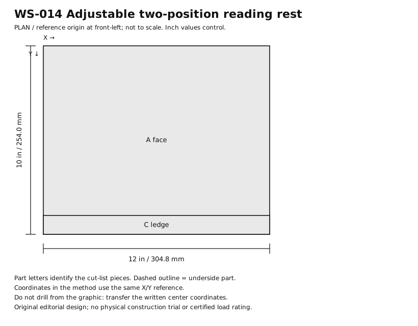
- Cut A 12 × 10, B 7 × 3, C 12 × 1, D 12 × 8 and two E 8 × 3/4 in, all measured 1/2 in plywood.
- Set A face up with its 12 in width horizontal. Fit C across its lower front edge so C projects 1/2 in above the face to catch the book; use three #6 × 3/4 in screws from behind at X = 1,6,11 in, centered on C.
- Connect the lower back edge of A to the front of D with two 1 in surface hinges at X = 2 and 10 in; use manufacturer-supplied 3/8 in screws that do not emerge through 1/2 in panels.
- Hinge B to the back of A on its vertical centerline, with B’s upper end 2 in below A’s top. Use a 1 in surface hinge and 3/8 in screws.
- Swing A up and B down onto D. With the actual closed manual in place, test two stable angles without drilling stop locations yet.
- Mark B’s foot contact line on D at each selected angle. The two marks must be at least 1 in apart and inside D’s rear edge by at least 1 in.
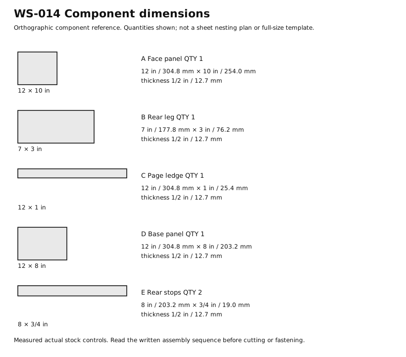
- Place each E immediately behind its corresponding foot line, centered across D. Fix each from under D using two #6 × 3/4 in screws at X = 3 and 9 in on that stop’s measured centerline.
- Mark the final measured Y coordinates beside both stops. The diagram gives panel sizes, while these two fit-selected coordinates are recorded at construction.
- Set B against one stop and load only the actual light manual. Turn pages slowly; move to the other position by unloading first.
- Fold the empty rest and check that hinges do not trap fingers or gouge another panel. If it tips or the leg disengages, do not use until redesigned.
Checks
- Three ledge screws have only 1/4 in penetration into C and no exposed points.
- Both selected foot lines are recorded and stops fit behind them.
- The actual light manual rests stably at both selected positions during a supervised trial.
Cleaning and maintenance
- Inspect hinges and ledge before use.
- Keep dry and unload before folding.
Primary context
These sources inform the context and do not endorse the original construction design.