Keep the earlier sealed cans at the accessible end while new cans are loaded behind them, without moving home-canning jars.
Original bounded component build. Dimensions describe this example, not an approved structural, occupied-building or universal fit design. Unbuilt / untested. US customary dimensions control.
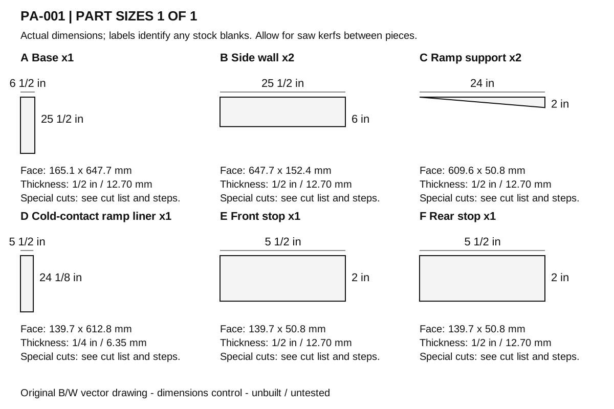
| Part | Quantity | Actual dimensions | Material / special cut |
|---|---|---|---|
| A Base | 1 | 6 1/2 in x 25 1/2 in x 1/2 in 165.1 x 647.7 x 12.7 mm | Sound untreated hardwood or exterior-bond plywood, actual measured thickness; reject split/warped stock Square ends; remove all splinters and burrs. |
| B Side wall | 2 | 25 1/2 in x 6 in x 1/2 in 647.7 x 152.4 x 12.7 mm | Sound untreated hardwood or exterior-bond plywood, actual measured thickness; reject split/warped stock Square ends; remove all splinters and burrs. |
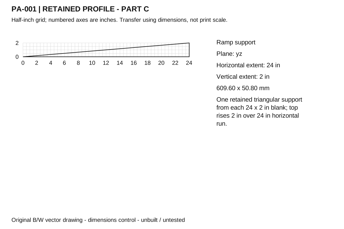
| C Ramp support | 2 | 24 in x 2 in x 1/2 in 609.6 x 50.8 x 12.7 mm | Sound untreated hardwood or exterior-bond plywood, actual measured thickness; reject split/warped stock One retained triangular support from each 24 x 2 in blank; top rises 2 in over 24 in horizontal run. |
| D Cold-contact ramp liner | 1 | 5 1/2 in x 24 1/8 in x 1/4 in 139.7 x 612.775 x 6.35 mm | Supplier-declared food-contact HDPE sheet, cold use only; no antimicrobial or certification claim for the finished build Square ends; remove all splinters and burrs. |
| E Front stop | 1 | 5 1/2 in x 2 in x 1/2 in 139.7 x 50.8 x 12.7 mm | Sound untreated hardwood or exterior-bond plywood, actual measured thickness; reject split/warped stock Square ends; remove all splinters and burrs. |
| F Rear stop | 1 | 5 1/2 in x 2 in x 1/2 in 139.7 x 50.8 x 12.7 mm | Sound untreated hardwood or exterior-bond plywood, actual measured thickness; reject split/warped stock Square ends; remove all splinters and burrs. |
Tape, square, pencil; clamped saw setup appropriate to the material; drill/driver and depth stop; countersink for wood fasteners; files/sanding block; clamps. Specific additional tools are noted in the steps.
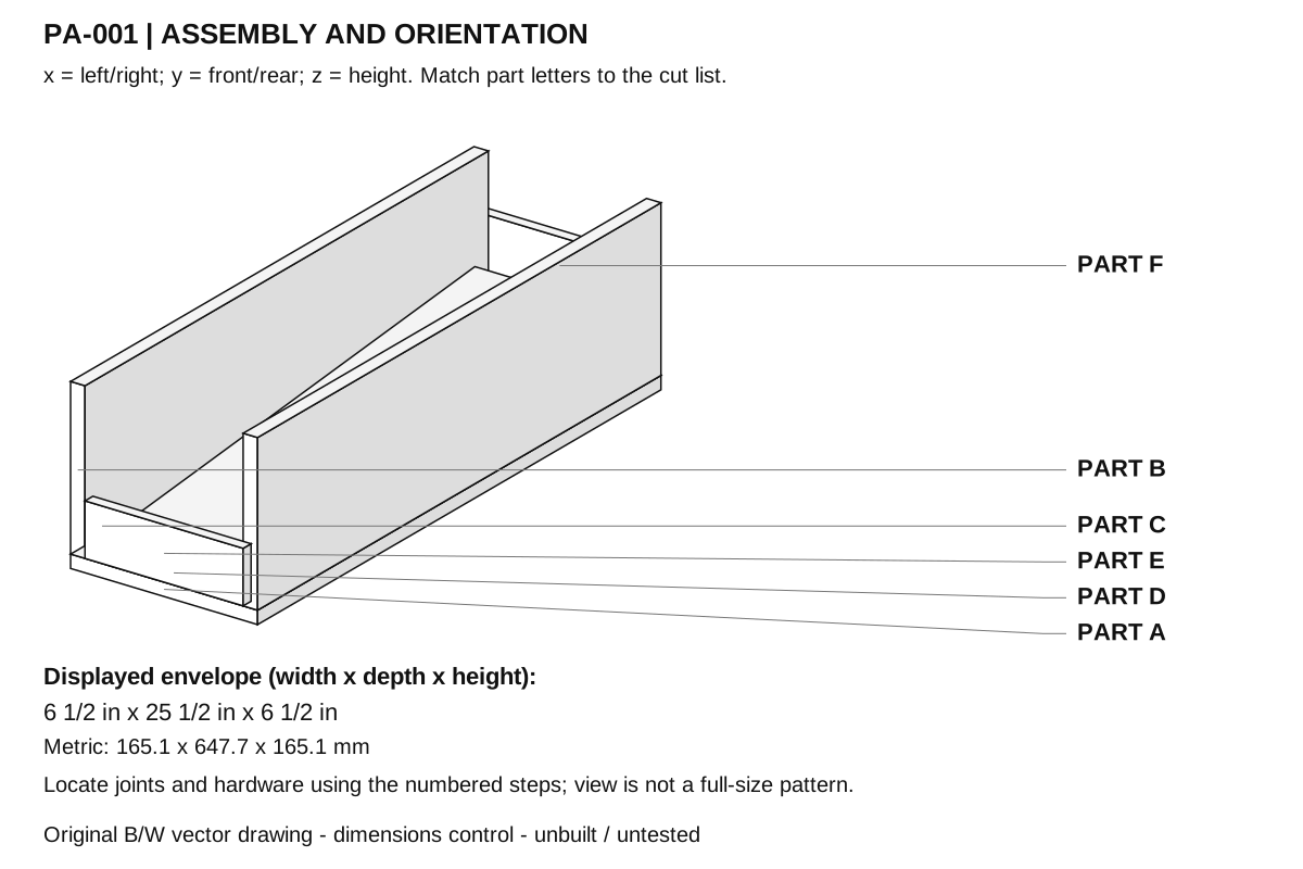
x=left/right, y=front/rear, z=up; origin is front-left underside unless stated
Retained segments with the same part/instance belong to one machined stock piece, not additional parts. Positions and sizes below are US inches; rotations are degrees.
| Part / instance | Origin x,y,z | Size / rotation |
|---|---|---|
| A / 1 | [0, 0, 0] | [6.5, 25.5, 0.5] / [0, 0, 0] |
| B / 1 | [0, 0, 0.5] | [0.5, 25.5, 6] / [0, 0, 0] |
| B / 2 | [6, 0, 0.5] | [0.5, 25.5, 6] / [0, 0, 0] |
| C / 1 | [0.5, 0.625, 0.5] | [0.5, 24, 2] / [0, 0, 0] |
| C / 2 | [5.5, 0.625, 0.5] | [0.5, 24, 2] / [0, 0, 0] |
| D / 1 | [0.5, 0.625, 0.5] | [5.5, 24.125, 0.25] / [4.763641690726177, 0, 0] |
| E / 1 | [0.5, 0, 0.5] | [5.5, 0.5, 2] / [0, 0, 0] |
| F / 1 | [0.5, 25, 2.5] | [5.5, 0.5, 2] / [0, 0, 0] |
Not a shelf-life extension method, seismic restraint or powered dispenser.
Reject bulging, leaking, rusty or badly dented containers according to food-safety guidance; the rack cannot establish food safety.
Inspect before each use for loose fasteners, cracked stock, damaged liners and a change in fit. Stop if a moving part binds or any sharp edge is exposed.
Remove debris before washing. Keep birds and food away during cleaning; follow the actual material/product cleaning instructions and dry completely before reuse.
Recheck screw seating after humidity changes. Replace damaged parts rather than hiding cracks with coating. No pressure, load, impact, disease-control or preservation performance is certified.
Purdue University Extension: Wood drying: FNR-37 Source
Utah State University Extension: Food Storage in Home Source
King Plastic Corporation: Food Service sheet materials Source