Garden · GA-038
Scion cutting support cradle
Locate a small scion stick on a stable sacrificial support while making careful hand-tool cuts away from the holding hand.
Editorial construction draft. Original digital diagrams; no physical build or load certification. Read dimensions, fit and use limits before making changes. US customary dimensions control; metric values are references.
Before marking and cutting
- Measure the stated stock sections before cutting. Use the cut-list geometry, not scale measurements from the drawing.
- US inch dimensions control; millimeter values are rounded conversions. Ordinary cut target ±1/16 in (1.6 mm); fit commercial accessories before boring attachment holes.
Use limits
- Original bounded garden component, not an occupied structure.
- No human standing, sitting, climbing, lifting or fall protection use. No stated safe working load.
- Geometry and fastener quantities are editorially checked; no prototype build, wind test or crop trial is claimed.
Materials and cuts
| Part | Qty | Size to cut | Material |
|---|---|---|---|
| P01 Base | 1 | 18 × 3 1/2 × 3/4 in 457.2 × 88.9 × 19.05 mm | 1 × 4 in board sound untreated cedar or other durable untreated wood |
| P02 V-block blank | 1 | 8 × 1 1/2 × 1 1/2 in 203.2 × 38.1 × 38.1 mm | 2 × 2 in board sound untreated wood |
| P03 Bench stop | 1 | 3 1/2 × 1 1/2 × 3/4 in 88.9 × 38.1 × 19.05 mm | 1 × 2 in board sound untreated cedar or other durable untreated wood; no unknown salvage |
Hardware and consumables
- 4 #8 × 1-1/2 in screws for V-block
- 2 #8 × 1-1/4 in screws for bench stop
- 2 bench clamps
- 1 replaceable sacrificial softwood strip 8 × 1 × 1/4 in
- Appropriate sharp hand tool with its own safe-use instructions
Tools
- Tape measure and steel rule
- Pencil, square and clamps
- Saw suited to the stated stock; eye and hearing protection
- Drill/driver, countersink and bits matched to fasteners
- Sandpaper and edge file; gloves when handling cut mesh
Assembly
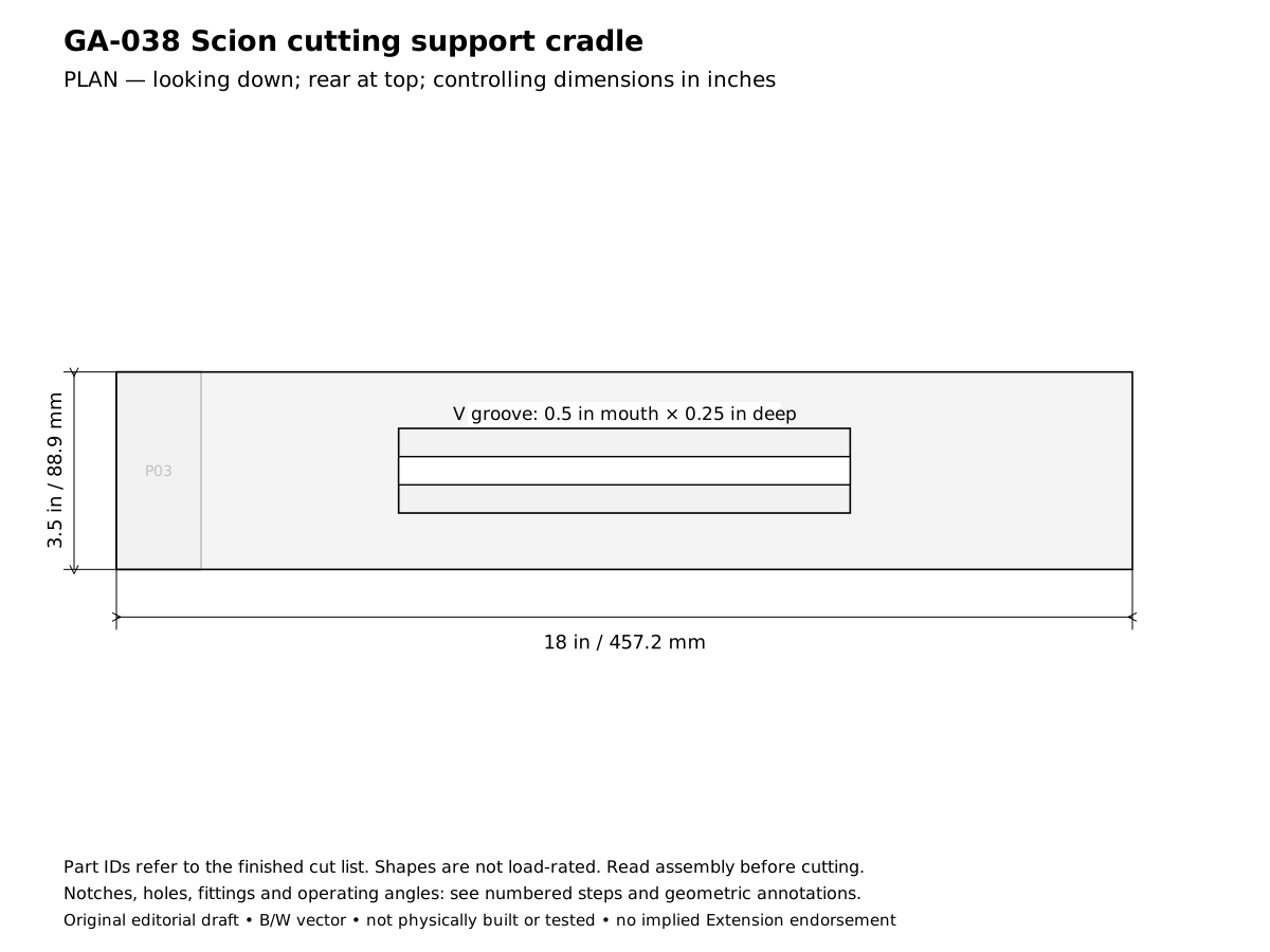
- Plan the scion cutting support cradle for this result: Locate a small scion stick on a stable sacrificial support while making careful hand-tool cuts away from the holding hand. Confirm the design reference before cutting: Groove 1/2 in wide × 1/4 in deep; no screws reach the cutting zone. In the drawings x runs left to right, y runs front to rear and z runs upward.
- Verify the required stock before laying out these parts: 1 × 2 in board: actual 0.75 × 1.5 in (19.05 × 38.1 mm); 1 × 4 in board: actual 0.75 × 3.5 in (19.05 × 88.9 mm); 2 × 2 in board: actual 1.5 × 1.5 in (38.1 × 38.1 mm). Reject split or twisted wood and unknown salvage; thinner stock requires recalculating the joints, not simply using the listed lengths.
- Cut and label the finished parts: 1 Base 18 × 3.5 × 0.75 in (457.2 × 88.9 × 19.05 mm), mark P01; 1 V-block blank 8 × 1.5 × 1.5 in (203.2 × 38.1 × 38.1 mm), mark P02; 1 Bench stop 3.5 × 1.5 × 0.75 in (88.9 × 38.1 × 19.05 mm), mark P03. Keep saw kerf outside each finished line. Rip only where the finished width is narrower than the actual stock; use a suitable guide and target ±1/16 in (1.6 mm) for ordinary cuts. Dowel triples mean length × diameter × diameter, not square dowel stock.
- Mark a V groove along the upper centerline of the 8 in block: 1/2 in mouth width and 1/4 in depth, with equal 45-degree sides.
- Clamp the block securely and cut the groove with a suitable guided hand tool. Do not attempt a freehand narrow table-saw cut.
- Sand the groove lightly and verify a scrap stick sits without rolling. Keep the block ends square.
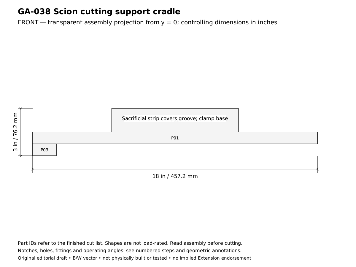
- Locate the V-block on the base at x = 5–13 in and y = 1–2-1/2 in. Drill four underside pilots, two near each block end.
- Attach the V-block with four 1-1/2 in screws, staying clear of the groove centerline. Confirm screw tips remain below the groove bottom.
- Attach the bench stop under the base at the front x = 0–1-1/2 in with two 1-1/4 in screws. Clamp both base ends to a stable bench before tool use.
- Place the sacrificial strip in the groove for short cuts and replace it as it becomes scored. Set the work so the cutting path points away from the holding hand and body.
- Practice with waste sticks and follow the chosen species-specific grafting technique separately. Stop if the stick can roll or requires the support hand in the blade path; this fixture does not make knife work risk-free.
- Complete the acceptance checks below before putting the assembly into service. Record any changed stock thickness, fastener or equipment fit on the project sheet. The published geometry has not been physically built or load-tested.
Checks
- Groove 1/2 in wide × 1/4 in deep; no screws reach the cutting zone.
- Both bench clamps engaged and sacrificial strip secure before use.
Operation
- Support fixture only, not a grafting success guarantee or instruction to cut toward a hand.
Cleaning and maintenance
- Remove shavings, replace the sacrificial strip and keep tools sheathed off the fixture.
Primary context
These sources inform the context and do not endorse the original construction design.