Garden · GA-039
Tabletop seed-winnowing baffle
Provide a removable wind shield and separate catch zones for small dry seed-cleaning trials outdoors.
Editorial construction draft. Original digital diagrams; no physical build or load certification. Read dimensions, fit and use limits before making changes. US customary dimensions control; metric values are references.
Before marking and cutting
- Measure the stated stock sections before cutting. Use the cut-list geometry, not scale measurements from the drawing.
- US inch dimensions control; millimeter values are rounded conversions. Ordinary cut target ±1/16 in (1.6 mm); fit commercial accessories before boring attachment holes.
Use limits
- Original bounded garden component, not an occupied structure.
- No human standing, sitting, climbing, lifting or fall protection use. No stated safe working load.
- Geometry and fastener quantities are editorially checked; no prototype build, wind test or crop trial is claimed.
Materials and cuts
| Part | Qty | Size to cut | Material |
|---|---|---|---|
| P01 Base | 1 | 30 × 18 × 1/2 in 762 × 457.2 × 12.7 mm | measured 1/2 in plywood exterior-bond plywood for protected non-food-contact fixtures; substitute thickness only by recalculating joints |
| P02 Rear baffle | 1 | 30 × 12 × 1/2 in 762 × 304.8 × 12.7 mm | measured 1/2 in plywood exterior-bond plywood for protected non-food-contact fixtures; substitute thickness only by recalculating joints |
| P03 Side baffle | 1 | 17 1/2 × 12 × 1/2 in 444.5 × 304.8 × 12.7 mm | measured 1/2 in plywood exterior-bond plywood for protected non-food-contact fixtures; substitute thickness only by recalculating joints |
| P04 Corner cleats | 2 | 12 × 1 1/2 × 3/4 in 304.8 × 38.1 × 19.05 mm | 1 × 2 in board sound untreated cedar or other durable untreated wood; no unknown salvage |
| P05 Divider strip | 1 | 17 1/2 × 1 1/2 × 3/4 in 444.5 × 38.1 × 19.05 mm | 1 × 2 in board sound untreated cedar or other durable untreated wood; no unknown salvage |
Hardware and consumables
- 12 #6 × 1 in screws for baffles, 6 each
- 8 #6 × 1 in screws for cleats
- 4 #6 × 1 in screws for divider
- 2 removable clean paper catch sheets, each about 14 × 17 in
- Two external table clamps; no powered fan included
Tools
- Tape measure and steel rule
- Pencil, square and clamps
- Saw suited to the stated stock; eye and hearing protection
- Drill/driver, countersink and bits matched to fasteners
- Sandpaper and edge file; gloves when handling cut mesh
Assembly
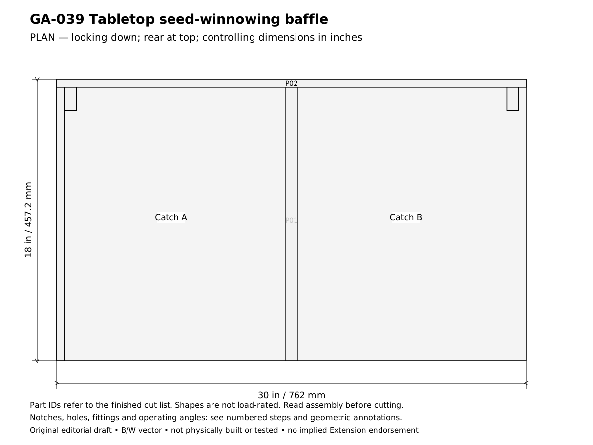
- Plan the tabletop seed-winnowing baffle for this result: Provide a removable wind shield and separate catch zones for small dry seed-cleaning trials outdoors. Confirm the design reference before cutting: Baffles square and supported by cleats; no exposed screw points. In the drawings x runs left to right, y runs front to rear and z runs upward.
- Verify the required stock before laying out these parts: 1 × 2 in board: actual 0.75 × 1.5 in (19.05 × 38.1 mm); measured 1/2 in plywood: measured thickness 0.5 in. Reject split or twisted wood and unknown salvage; thinner stock requires recalculating the joints, not simply using the listed lengths.
- Cut and label the finished parts: 1 Base 30 × 18 × 0.5 in (762 × 457.2 × 12.7 mm), mark P01; 1 Rear baffle 30 × 12 × 0.5 in (762 × 304.8 × 12.7 mm), mark P02; 1 Side baffle 17.5 × 12 × 0.5 in (444.5 × 304.8 × 12.7 mm), mark P03; 2 Corner cleats 12 × 1.5 × 0.75 in (304.8 × 38.1 × 19.05 mm), mark P04; 1 Divider strip 17.5 × 1.5 × 0.75 in (444.5 × 38.1 × 19.05 mm), mark P05. Keep saw kerf outside each finished line. Rip only where the finished width is narrower than the actual stock; use a suitable guide and target ±1/16 in (1.6 mm) for ordinary cuts. Dowel triples mean length × diameter × diameter, not square dowel stock.
- Mark the rear baffle at y = 17-1/2 in and the side baffle at x = 0. They sit on top of the base and form an L-shaped shield.
- Fit the two 12 in cleats inside the rear baffle at x = 1/2 and 28-3/4 in. Their faces support the thin panel without leaving screw points exposed.
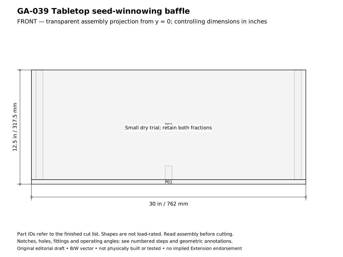
- Attach rear baffle through its face into the cleats using four 1 in screws per cleat. Keep the lower edges flush at z = 1/2 in.
- Fasten the rear assembly from beneath the base with six 1 in screws into the baffle/cleat feet, distributing four into solid cleat material and two into the panel edge with careful pilot holes.
- Fasten the side baffle with six 1 in underside screws into its edge. Add a temporary clamp at the rear corner while tightening so the L stays square.
- Install the center divider on the base at x = 14-5/8 in with four underside screws. Set one loose clean catch sheet on each side.
- Clamp the base to a stable outdoor table away from food and people. Trial a spoonful of already dry seed/chaff with gentle natural air; do not add a power fan or inhale dust.
- Pour only a short distance over the catch area and inspect both fractions. Adjust orientation and repeat on a small trial; retain all fractions until viable seed recovery is confirmed. Species-specific cleaning methods remain separate.
- Complete the acceptance checks below before putting the assembly into service. Record any changed stock thickness, fastener or equipment fit on the project sheet. The published geometry has not been physically built or load-tested.
Checks
- Baffles square and supported by cleats; no exposed screw points.
- Both catch sheets removable and labeled; no seed discarded until inspected.
Operation
- Not a calibrated seed cleaner, airflow device or guarantee of purity/viability. Avoid allergenic or dusty unknown materials.
Cleaning and maintenance
- Clean between lots, retain labels and dry before stacking.
Primary context
These sources inform the context and do not endorse the original construction design.