Garden · GA-050
Fixed-height mulch spreading screed
Draw loose mulch to an example 1-1/2 in layer between two skids resting on firm reference surfaces.
Editorial construction draft. Original digital diagrams; no physical build or load certification. Read dimensions, fit and use limits before making changes. US customary dimensions control; metric values are references.
Before marking and cutting
- Measure the stated stock sections before cutting. Use the cut-list geometry, not scale measurements from the drawing.
- US inch dimensions control; millimeter values are rounded conversions. Ordinary cut target ±1/16 in (1.6 mm); fit commercial accessories before boring attachment holes.
Use limits
- Original bounded garden component, not an occupied structure.
- No human standing, sitting, climbing, lifting or fall protection use. No stated safe working load.
- Geometry and fastener quantities are editorially checked; no prototype build, wind test or crop trial is claimed.
Materials and cuts
| Part | Qty | Size to cut | Material |
|---|---|---|---|
| P01 Leveling blade | 1 | 36 × 2 1/2 × 3/4 in 914.4 × 63.5 × 19.05 mm | 1 × 3 in board sound untreated cedar or other durable untreated wood |
| P02 Skids | 2 | 10 × 3 1/2 × 1 1/2 in 254 × 88.9 × 38.1 mm | 2 × 4 in board sound untreated wood |
| P03 Hand grips | 2 | 8 × 1 1/2 × 3/4 in 203.2 × 38.1 × 19.05 mm | 1 × 2 in board sound untreated cedar or other durable untreated wood; no unknown salvage |
Hardware and consumables
- 4 #9 × 3 in screws for blade/skid joints, 2 per skid
- 8 #8 × 1-1/4 in screws for grips, 4 each
Tools
- Tape measure and steel rule
- Pencil, square and clamps
- Saw suited to the stated stock; eye and hearing protection
- Drill/driver, countersink and bits matched to fasteners
- Sandpaper and edge file; gloves when handling cut mesh
Assembly
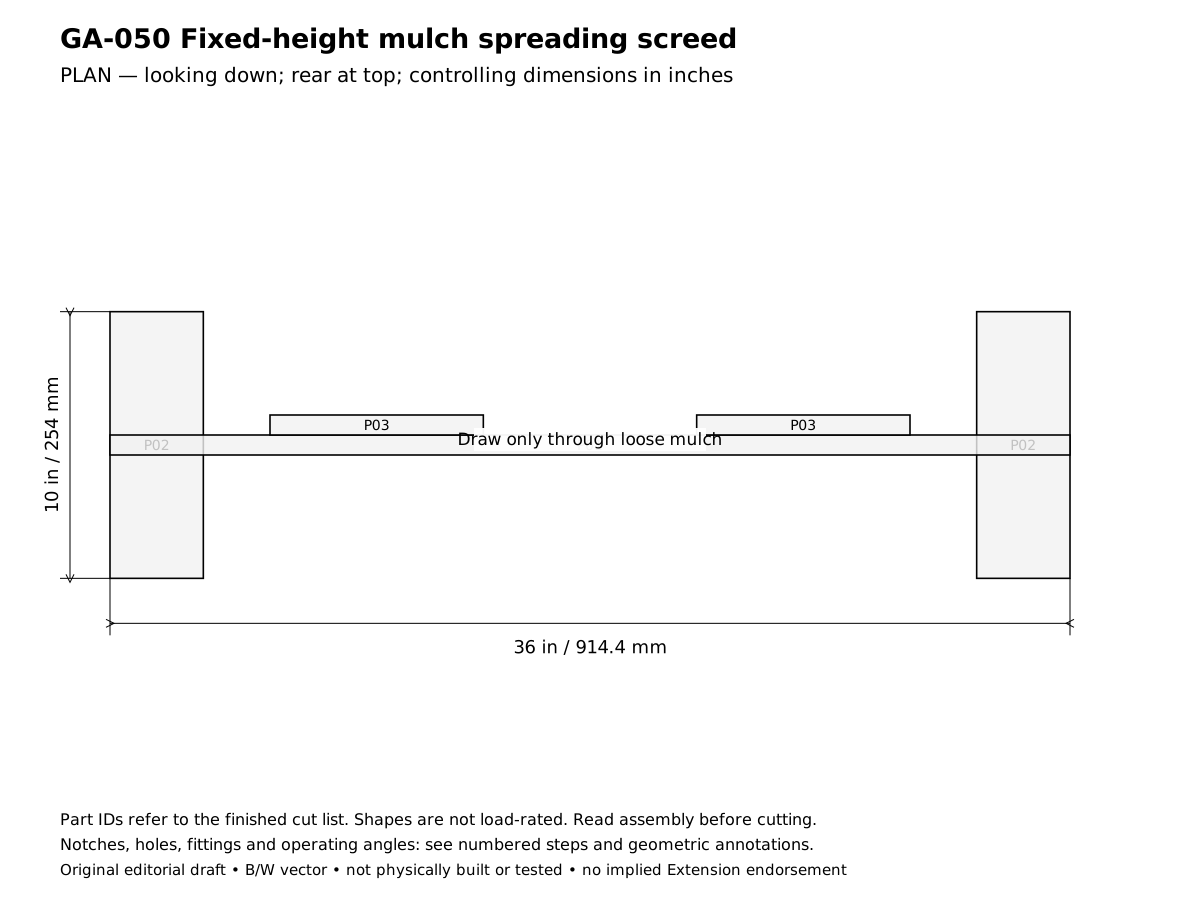
- Plan the fixed-height mulch spreading screed for this result: Draw loose mulch to an example 1-1/2 in layer between two skids resting on firm reference surfaces. Confirm the design reference before cutting: Blade lower edge 1-1/2 in (38.1 mm) above both skid bottoms. In the drawings x runs left to right, y runs front to rear and z runs upward.
- Verify the required stock before laying out these parts: 1 × 2 in board: actual 0.75 × 1.5 in (19.05 × 38.1 mm); 1 × 3 in board: actual 0.75 × 2.5 in (19.05 × 63.5 mm); 2 × 4 in board: actual 1.5 × 3.5 in (38.1 × 88.9 mm). Reject split or twisted wood and unknown salvage; thinner stock requires recalculating the joints, not simply using the listed lengths.
- Cut and label the finished parts: 1 Leveling blade 36 × 2.5 × 0.75 in (914.4 × 63.5 × 19.05 mm), mark P01; 2 Skids 10 × 3.5 × 1.5 in (254 × 88.9 × 38.1 mm), mark P02; 2 Hand grips 8 × 1.5 × 0.75 in (203.2 × 38.1 × 19.05 mm), mark P03. Keep saw kerf outside each finished line. Rip only where the finished width is narrower than the actual stock; use a suitable guide and target ±1/16 in (1.6 mm) for ordinary cuts. Dowel triples mean length × diameter × diameter, not square dowel stock.
- Place the 10 in skids flat and parallel at x = 0–3-1/2 and 32-1/2–36 in. Their upper faces are 1-1/2 in above the reference surface.
- Stand the 36 in blade across the skids at y = 4-5/8–5-3/8 in. Its lower edge rests on the skid tops, setting the example layer height.
- Clamp the blade square to both skids. Mark two underside screw centers per skid at x = 3/4 and 2-3/4 in from the outside end, y = 5 in.
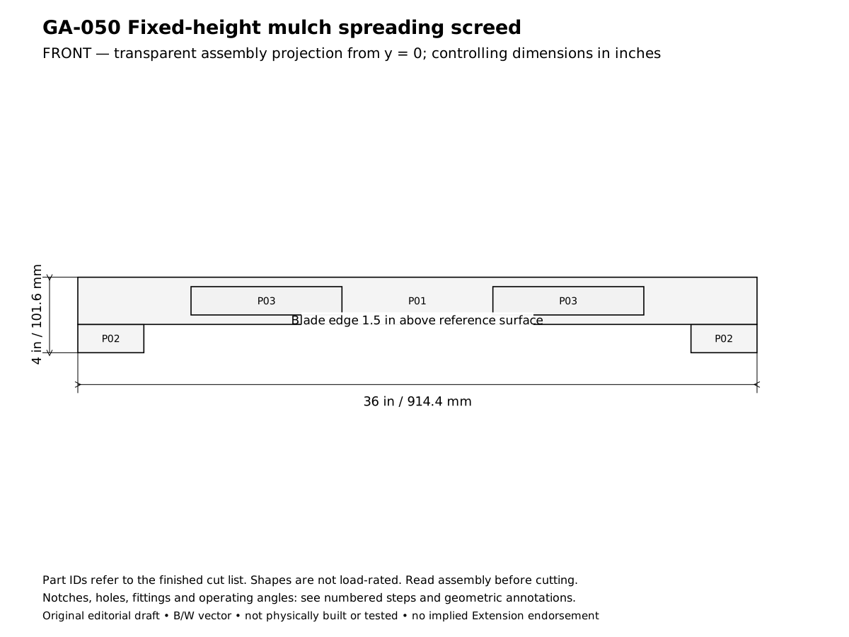
- Drill upward through each skid into the blade lower edge, using a guide to stay centered in its 3/4 in thickness. Drive four 3 in screws without splitting the blade.
- Attach the two 8 in grips to the blade rear face at x = 6–14 and 22–30 in, z = 2–3-1/2 in. Use four 1-1/4 in screws per grip from the front.
- Round skid leading ends and blade corners. Check that the blade lower edge remains parallel to the skid bottoms.
- Place the skids on firm level reference strips beside a small loose-mulch trial and pull with both hands. Do not force through stones, roots or established stems.
- Measure the finished layer and compare with the crop/site recommendation. The 1-1/2 in construction example is not a universal mulch depth, and loose mulch will settle.
- Complete the acceptance checks below before putting the assembly into service. Record any changed stock thickness, fastener or equipment fit on the project sheet. The published geometry has not been physically built or load-tested.
Checks
- Blade lower edge 1-1/2 in (38.1 mm) above both skid bottoms.
- Skids parallel and all screws buried; trial measured after spreading.
Operation
- Loose-mulch hand tool only, not soil grading, compaction or a vehicle-drawn implement.
Cleaning and maintenance
- Brush and dry; check skid wear that changes the example layer height.
Primary context
These sources inform the context and do not endorse the original construction design.