Poultry · PO-004
Manual sliding pop-door track assembly
Close an existing 14 × 14 in bird opening with a removable upward-sliding panel, using a positive latch rather than a hanging cord.
Editorial construction draft. Original digital diagrams; no physical build or load certification. Read dimensions, fit and use limits before making changes. US customary dimensions control; metric values are references.
Before marking and cutting
- Read every step and identify the installed orientation. Make the component off-site with birds excluded.
- Measure the actual receiving space, chosen commercial accessories and access route. Stop if the example does not fit; changing only one member can invalidate the assembly.
- Reject split, warped, moldy or chemically contaminated stock. Keep exposed mesh cut ends and all sharp fasteners inaccessible to birds.
- The drawing dimensions control; illustrations are not full-size templates. Allow a saw kerf between parts when laying out stock.
Use limits
- Example fits only the defined existing opening and mounting zone; do not leave birds unattended until operation and actual fit are observed.
- No automatic actuator, electrical wiring, hanging rope or counterweight is included.
- This component has no predator-resistance test or structural wall approval.
Materials and cuts
| Part | Qty | Size to cut | Material |
|---|---|---|---|
| A Wall backing rail | 2 | 38 × 2 1/2 × 3/4 in 965.2 × 63.5 × 19.05 mm | Untreated sound straight softwood. Square ends; remove splinters. |
| B Outer track spacer | 2 | 38 × 3/4 × 3/4 in 965.2 × 19.05 × 19.05 mm | Untreated sound straight softwood. Square ends; remove splinters. |
| C Front keeper rail | 2 | 38 × 2 1/2 × 3/4 in 965.2 × 63.5 × 19.05 mm | Untreated sound straight softwood. Square ends; remove splinters. |
| D Sliding leaf | 1 | 20 1/4 × 18 × 1/2 in 514.35 × 457.2 × 12.7 mm | Exterior-bond plywood, measured actual thickness. Square ends; remove splinters. |
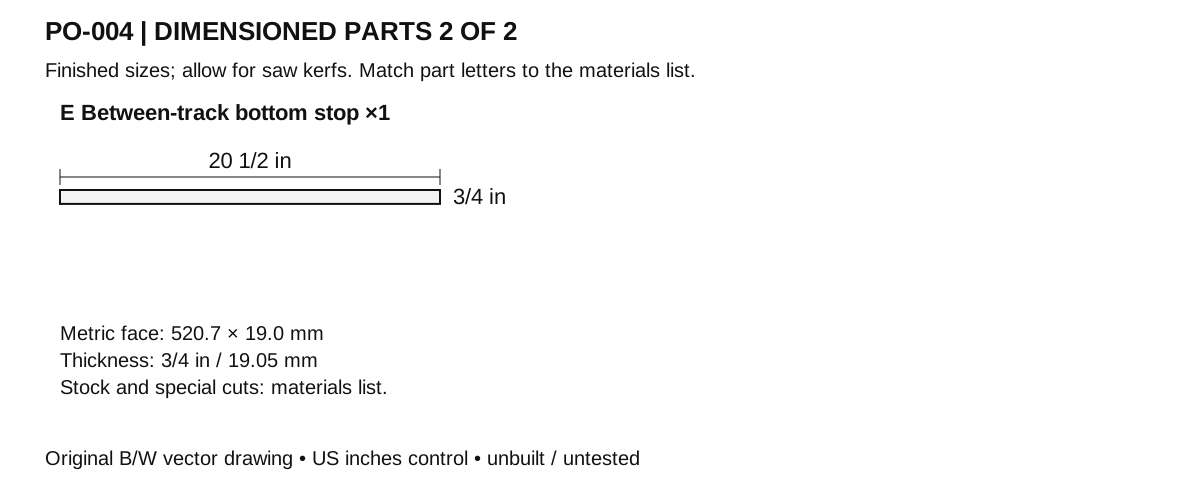
| E Between-track bottom stop | 1 | 20 1/2 × 3/4 × 3/4 in 520.7 × 19.05 × 19.05 mm | Untreated sound straight softwood. Square ends; remove splinters. |
Hardware and consumables
- 8 × #8 corrosion-resistant exterior wood screw 1 1/4 in (31.75 mm). Spacer to backing [N1]
- 10 × #8 corrosion-resistant exterior wood screw 2 in (50.8 mm). Keeper through spacer into backing [N1]
- 2 × #8 corrosion-resistant exterior wood screw 1 1/2 in (38.1 mm). Bottom stop [N1]
- 2 × Positive captive pin latches. Separate closed and fully raised positions
- 1 × Door pull and smooth-ended through-bolts. Maker-specific, short enough to avoid bird contact
- 1 × Substrate-specific backing anchors. Quantity and type determined from actual existing wall; not included in the screw count
- N1 applies to every entry marked [N1]: Use compatible coatings/metals and the maker's pilot-hole guidance; do not substitute drywall screws.
Tools
- Tape measure, square and pencil
- Saw appropriate to material and work supports
- Drill/driver, countersink and pilot bits selected for the screws
- Clamps, sanding block and eye/hearing protection; dust control appropriate to the material
Assembly
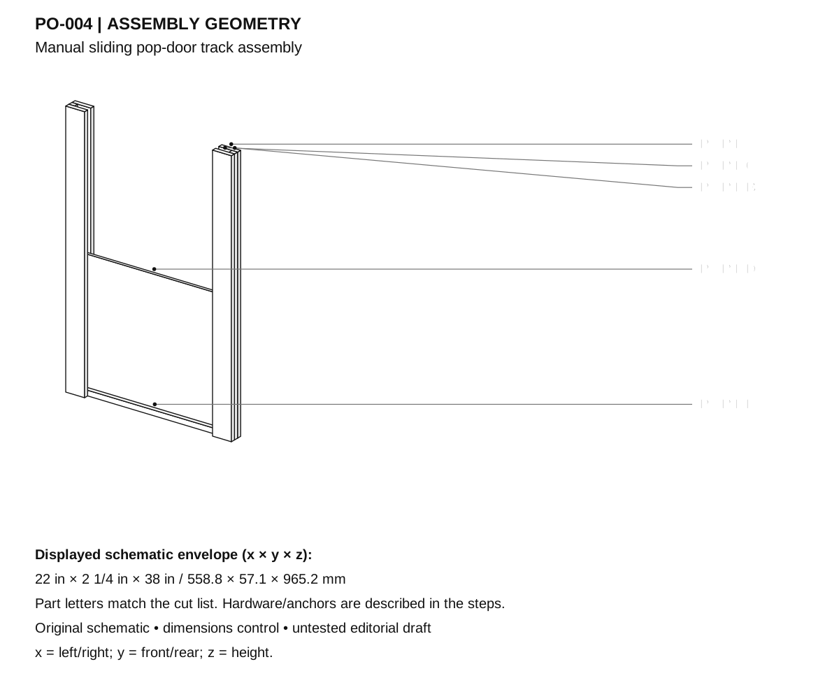
- Confirm an already framed, finished 14 × 14 in (355.6 × 355.6 mm) opening. This plan does not authorize cutting studs or altering a structural wall.
- Establish a 22 in (558.8 mm) wide by 38 in (965.2 mm) high mounting zone; the opening runs from x = 4 to 18 in and z = 2 to 16 in relative to its lower-left corner.
- Cut A, B and C to 38 in. Sand their edges; keep the two spacer B strips an accurate 3/4 in (19.1 mm) wide and thick.
- Attach A to the inspected supporting wall, with the left rail x = 0–2 1/2 in and the right x = 19 1/2–22 in. Use site-selected fasteners appropriate to the actual substrate; thin siding alone is not an anchor.
- Place B on the far outside edge of each A. Fix each B with four 1 1/4 in screws, 2 in (50.8 mm) from its ends and at two evenly spaced intermediate positions.
- Cut E to 20 1/2 in (520.7 mm). Fit it horizontally between B at their lower ends, on A's front plane; attach at its ends through the spacers with one 1 1/2 in screw per end.
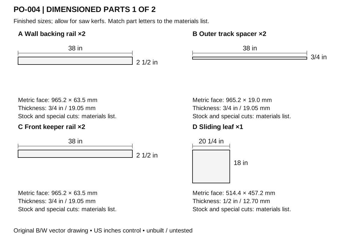
- Cut D to 20 1/4 × 18 in (514.4 × 457.2 mm), ease its corners, and seal/cure all edges before fitting it into the 20 1/2 in wide track cavity.
- Fix C over each B with five 2 in screws on the B centerline. C overlaps the sliding leaf's edges; it must not pinch the leaf against A.
- Test the leaf at full travel: closed lower edge z = 3/4 in; raised lower edge z = 16 3/4 in (425.5 mm), which clears the opening. The raised top remains below the 38 in track end.
- Fit a bought handle with short through-bolts and smooth nuts, then install one positive pin latch for the closed position and a separate captive stop pin for the fully raised position; hardware holes must stay outside the bird passage.
- Cycle the door 20 times by hand without birds. Confirm 1/8 in (3.2 mm) side clearance per edge, no pinch, full closure onto E and independent retention when raised.
- Supervise first use. Never rely on friction, a dangling lift cord or this wood panel alone as a certified predator barrier; inspect and latch it on the actual flock schedule.
Checks
- A rails are parallel; their outer faces span 22 in. The inner B faces span 20 1/2 in.
- The leaf cavity is 3/4 in deep around a 1/2 in panel, leaving 1/4 in (6.4 mm) total running depth.
- Raised and closed positive retainers engage without hand support and cannot fall into the passage.
- No cord loop, sharp bolt, pinch point accessible from the bird side or unguarded opening remains.
Cleaning and maintenance
- Inspect before each use for splits, loose joints, protruding points and trapped debris.
- Remove accumulated litter or manure promptly. When cleaning is needed, move birds away, remove debris first, wash and use only a suitable label-directed product if disinfection is indicated; let the item dry before return.
- Recheck the fit after seasonal wood movement. Replace cracked panels, rusted fasteners or frayed liners instead of concealing damage.
- Sand accessible edges to a small smooth radius. Use a removable washable contact liner where specified. Any optional coating must be suitable for the intended animal-equipment use and fully cured according to its label before installation. Porous wood is not represented as a disinfectable food-contact surface.
Primary context
These sources inform the context and do not endorse the original construction design.