Poultry · PO-022
Dedicated manure-tool wall dock
Hang dedicated scrapers and light cleaning tools in separated bays so they do not occupy the clean egg-handling area.
Editorial construction draft. Original digital diagrams; no physical build or load certification. Read dimensions, fit and use limits before making changes. US customary dimensions control; metric values are references.
Before marking and cutting
- Read every step and identify the installed orientation. Make the component off-site with birds excluded.
- Measure the actual receiving space, chosen commercial accessories and access route. Stop if the example does not fit; changing only one member can invalidate the assembly.
- Reject split, warped, moldy or chemically contaminated stock. Keep exposed mesh cut ends and all sharp fasteners inaccessible to birds.
- The drawing dimensions control; illustrations are not full-size templates. Allow a saw kerf between parts when laying out stock.
Use limits
- No person may stand or sit on this component. No tested load rating is claimed.
- A site-specific safe location and supervision are required; remove it if birds become trapped, peck damaged material, or cannot use their normal feed, water, shelter and escape routes.
Materials and cuts
| Part | Qty | Size to cut | Material |
|---|---|---|---|
| A Backboard | 1 | 30 × 12 × 3/4 in 762 × 304.8 × 19.05 mm | Exterior-bond plywood, measured actual thickness. Square ends; remove splinters. |
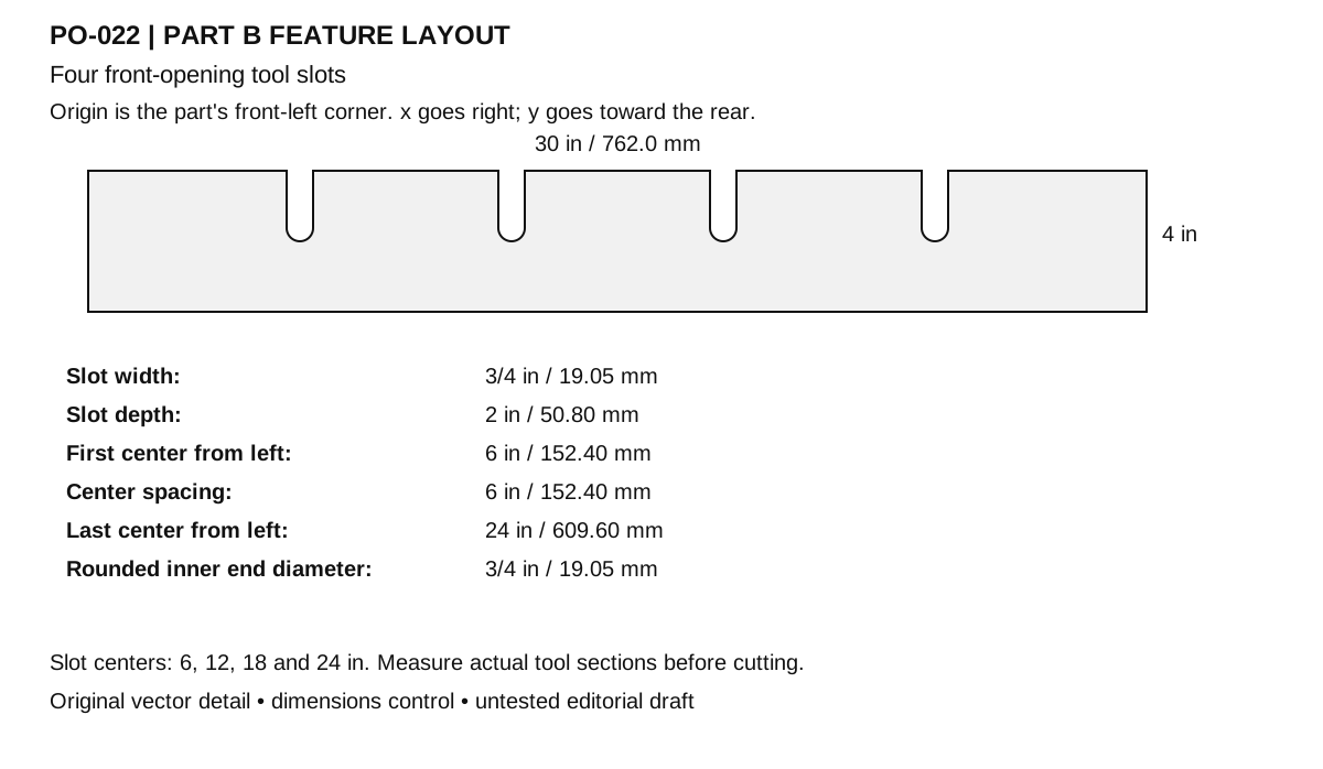
| B Projecting dock shelf | 1 | 30 × 4 × 3/4 in 762 × 101.6 × 19.05 mm | Exterior-bond plywood, measured actual thickness. Cut four 3/4 in wide, 2 in deep front-opening slots centered at x = 6, 12, 18 and 24 in; radius inner slot ends. |
| C Shelf support cleat | 1 | 30 × 1 1/2 × 3/4 in 762 × 38.1 × 19.05 mm | Untreated sound straight softwood. Square ends; remove splinters. |
Hardware and consumables
- 10 × #8 corrosion-resistant exterior wood screw 1 1/4 in (31.75 mm). Back-to-cleat and shelf-to-cleat. Use compatible coatings/metals and the maker's pilot-hole guidance; do not substitute drywall screws.
- 2 × Corrosion-resistant shelf bracket with compatible short screws. Fit actual backing and 4 in shelf depth
- 4 × Substrate-specific wall anchor. Select from actual backing and intended tools
Tools
- Tape measure, square and pencil
- Saw appropriate to material and work supports
- Drill/driver, countersink and pilot bits selected for the screws
- Clamps, sanding block and eye/hearing protection; dust control appropriate to the material
Assembly
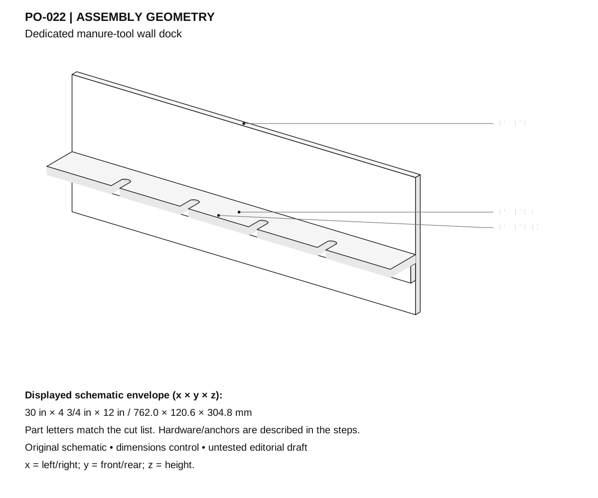
- Select a dirty-equipment wall outside bird reach and separate from clean cartons, feed scoops and protective clothing.
- Measure intended tools: handle sections at the dock must pass through a 3/4 in (19.1 mm) slot and tool heads must be broad enough not to fall through; long heavy shovels need their own rated holder.
- Cut A to 30 × 12 in (762 × 304.8 mm), B to 30 × 4 in, and C to 30 × 1 1/2 in, all actual 3/4 in thick.
- Mark slot centerlines on B at 6, 12, 18 and 24 in. Drill a 3/4 in end hole with its center 1 5/8 in (41.3 mm) from the front edge, then saw straight from the front to meet it.
- The finished slot depth is 2 in (50.8 mm); sand the inside ends and edges so handles are not cut or snagged.
- Clamp C onto A with C's lower edge 3 in above A's bottom and its upper edge at 4 1/2 in. Drive five 1 1/4 in screws through A into C, evenly spaced.
- Place B with its rear edge against A and underside resting on C at z = 4 1/2 in. Drive five 1 1/4 in screws down into C.
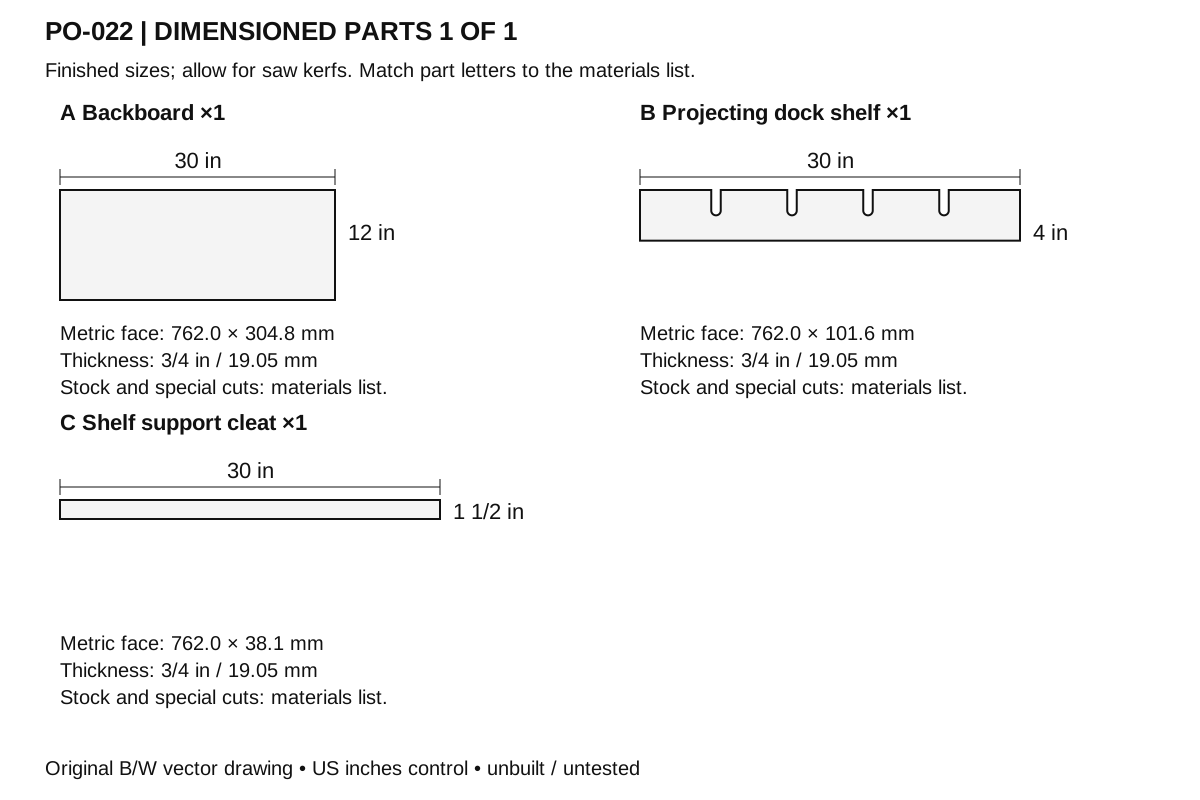
- Add two corrosion-resistant shelf brackets below B at x = 6 and 24 in. Fit maker-compatible short screws to B and sound backing; bracket hardware must not enter the slots.
- Drill four mounting holes in A, 2 in from the corners. Choose anchors for the inspected existing support and the actual tools; do not mount to unsupported thin siding.
- Mount level and hang the intended light tools one at a time. Check heads seat on B and no tool can slide accidentally through a slot.
- Label the dock for dedicated dirty tools, with labels on the human side; keep manure-contact ends from touching clothing or clean supplies.
- Remove tools, scrape debris into waste collection and clean/dry the shelf/slots regularly. A dedicated dock does not replace actual tool cleaning.
Checks
- Slots are 3/4 in wide, 2 in deep and centered at the stated 6 in spacing.
- Shelf underside sits at z = 4 1/2 in, on the cleat rather than on end-grain screws alone.
- Actual tools hang securely without exposed points or obstruction of a passage.
- Wall support and selected bracket capacity are checked for the actual tools; no general load rating is claimed.
Cleaning and maintenance
- Inspect before each use for splits, loose joints, protruding points and trapped debris.
- Remove accumulated litter or manure promptly. When cleaning is needed, move birds away, remove debris first, wash and use only a suitable label-directed product if disinfection is indicated; let the item dry before return.
- Recheck the fit after seasonal wood movement. Replace cracked panels, rusted fasteners or frayed liners instead of concealing damage.
- Sand accessible edges to a small smooth radius. Use a removable washable contact liner where specified. Any optional coating must be suitable for the intended animal-equipment use and fully cured according to its label before installation. Porous wood is not represented as a disinfectable food-contact surface.
Primary context
These sources inform the context and do not endorse the original construction design.