Workshop · WS-003
Right-angle glue-up corner fixture
Hold two light frame members at a verified right angle while separate clamps apply glue-up pressure.
Editorial construction draft. Original digital diagrams; no physical build or load certification. Read dimensions, fit and use limits before making changes. US customary dimensions control; metric values are references.
Before marking and cutting
- US inches; feet where appropriate. Metric values are rounded references. Written inch values control.
- 3/4 in means measured 0.750 in actual thickness wherever used. Recalculate mating lengths for other sheet thicknesses; do not substitute nominal stock blindly.
Use limits
- For the bounded stated manual task. Do not install it on a powered machine or use it to replace a guard.
- No load, measurement-certification or protective-equipment claim.
Materials and cuts
| Part | Qty | Size to cut | Material |
|---|---|---|---|
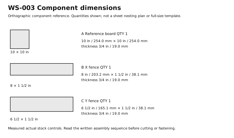
| A Reference board | 1 | 10 × 10 × 3/4 in 254 × 254 × 19.05 mm | Sanded birch plywood with sound, void-free receiving edges. Measured actual thickness 3/4 in. |
| B X fence | 1 | 8 × 1 1/2 × 3/4 in 203.2 × 38.1 × 19.05 mm | Clear solid hard maple, straight grain along the listed length. Measured actual thickness 3/4 in. |
| C Y fence | 1 | 6 1/2 × 1 1/2 × 3/4 in 165.1 × 38.1 × 19.05 mm | Clear solid hard maple, straight grain along the listed length. Measured actual thickness 3/4 in. |
Hardware and consumables
- 6 × Compatible wood screws. Selected length, pilots and locations are stated in the instructions; test on actual scrap.
Tools
- Rule with fractional inches
- Pencil or appropriate material marker
- Reliable square
- Saw suited to the specified stock
- Clamps
- Abrasive and dust-removal brush
- Drill with the specified bit and depth stop where needed
- Driver matching selected fasteners
Assembly
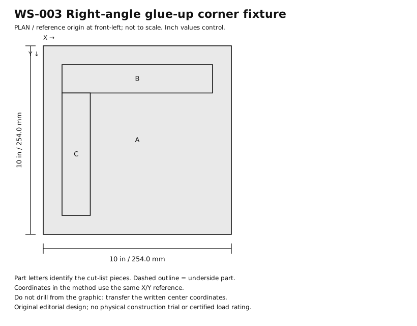
- This fixture locates a corner; separate clamps carry the clamping force. Cover the contact area with removable release tape when using wood adhesive.
- Cut A to 10 in / 254.0 mm by 10 in / 254.0 mm from flat measured 3/4 in stock. Mark one face UP and mark front-left X0 Y0; remove only the splinters, not the reference edges.
- Draw the centerline and attachment footprints from the part positions below. Measure from the reference faces each time; do not add a chain of rounded conversions.
- Cut B 8 × 1 1/2 × 3/4 in and C 6 1/2 × 1 1/2 × 3/4 in. C runs along Y, so its plan footprint is 1 1/2 × 6 1/2 in.
- Clamp B at X = 1–9, Y = 1–2 1/2 in. Clamp C at X = 1–2 1/2, Y = 2 1/2–9 in. The inside faces Y = 2 1/2 and X = 2 1/2 form the working corner.
- Dry-fit and clamp the assembly on a stable surface. Check the intended article against the clearances before drilling or gluing; correct the layout on paper if it does not fit.
- Drill from beneath A at (2,1 3/4),(5,1 3/4),(8,1 3/4) in into B, then at (1 3/4,3 1/2),(1 3/4,6),(1 3/4,8) in into C. Use six #8 × 1 1/4 in screws with clearance holes and centered pilots.
- Ease exposed corners and all edges that the operator will touch. Remove dust and any projecting point; countersink only to a flush head.
- Check the two inside faces with a reliable square over their full contact length. Do not use the outside cut edges as the acceptance reference.
- Fit two scrap frame members to the inside faces. Place independent clamps so they do not pull the board upward or put a hand in a pinch point.
- Apply a small amount of adhesive to a test joint, add release tape beneath it and close the independent clamps gently.
- Remove the test after the adhesive cure time. Check the joint square and remove any hardened glue that could change the fence seating.
Checks
- Working inside reference is X = 2 1/2, Y = 2 1/2 in; fences meet without an inside obstruction.
- Both members contact their fence continuously and a completed scrap joint checks square.
- Assembly is flat and free of splinters, exposed tips and loose parts.
- A second operator can repeat the intended light-duty operation without being coached.
Cleaning and maintenance
- Brush or wipe the unloaded assembly clean after use.
- Inspect attachment fit and fasteners before each new task.
- Replace a damaged contact surface; recheck the reference dimensions after repair.
Primary context
These sources inform the context and do not endorse the original construction design.