Shape a small nonstructural laminated wood arch between matched curved forms using separate commercial clamps.
Before cutting
US inches control. Metric values are rounded references. X runs left to right; Y runs away from the front, or Z upward in elevation, as stated in each view.
All thicknesses are actual, not nominal. Verify stock before cutting; do not substitute thinner sheet stock without recalculating joints. Rough blanks include trimming allowance, not saw kerf.
Use limits
Cold forming of a small nonstructural scrap arch only; no load rating, guaranteed bond pressure, springback or service life.
Adhesive/clamp maker requirements control. No heat, pressure vessel, archery use, occupied structure or engineered component.
Materials and cuts
Part
Qty
US / metric
Actual stock and profile
A Male-form layers
5
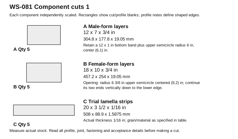
12 x 7 x 3/4 in 304.8 x 177.8 x 19.05 mm
Flat void-free birch plywood; measure and machine to the listed ACTUAL thickness. Retain a 12 x 1 in bottom band plus upper semicircle radius 6 in, center (6,1) in.
B Female-form layers
5
18 x 10 x 3/4 in 457.2 x 254 x 19.05 mm
Flat void-free birch plywood; measure and machine to the listed ACTUAL thickness. Opening: radius 6 3/8 in upper semicircle centered (9,2) in; continue its two ends vertically down to the lower edge.
C Trial lamella strips
5
20 x 3 1/2 x 1/16 in 508 x 88.9 x 1.5875 mm
Clear straight-grained ash veneer strips, actual 1/16 in; long grain along 20 in; no checks or cross-grain.
Hardware
1 x Wood adhesive. Full labeled cure for stacked plywood forms. The trial laminate uses an adhesive whose maker permits the intended cold wood lamination; its requirements control.
2 x Release film. Thin clean sheets covering both curved form surfaces; actual combined laminate/adhesive/film stack must not exceed the 3/8 in radial gap.
3 x Commercial bar clamps. Minimum 10 in opening and 2 in usable throat; intact, used by maker instructions. No clamp load or cured-arch capacity is derived.
Tools
Fractional-inch rule and reliable square; Pencil, awl and clamps; Handsaw or appropriate guarded stock-cutting tool; Drill, matched bits and positive depth stop where specified; Files, abrasive and driver matching hardware; Eye protection and dust control appropriate to material and tool; Paper knife/scissors, folding bone and blunt sewing needle where specified
Construction
Cut five A blanks 12 x 7 x 3/4 in and five B 18 x 10 x 3/4 in. Machine all actual thicknesses consistently so each finished form stack is 3 3/4 in deep.
On each A face mark center (6,1) in and draw an upper semicircle radius 6 in. Retain everything below that arc down to the Y0 edge, including the 12 x 1 in bottom band; remove the two upper corner wastes.
On each B mark center (9,2) in and the upper semicircle radius 6 3/8 in. Remove the material BELOW that arc, with vertical cut lines from its ends (2 5/8,2) and (15 3/8,2) in down to Y0. Keep both outer legs and the solid top bridge.
Saw outside each retained profile and smooth to the marks using a shared paper template. Stack each set dry and correct high spots so all five layers register without steps at the curved contact edge.
Glue each five-layer form separately using the adhesive label and independent clamps, keeping all curved profiles flush. Allow the full cure, then fair each 3 3/4 in deep curved face without changing its intended radius.
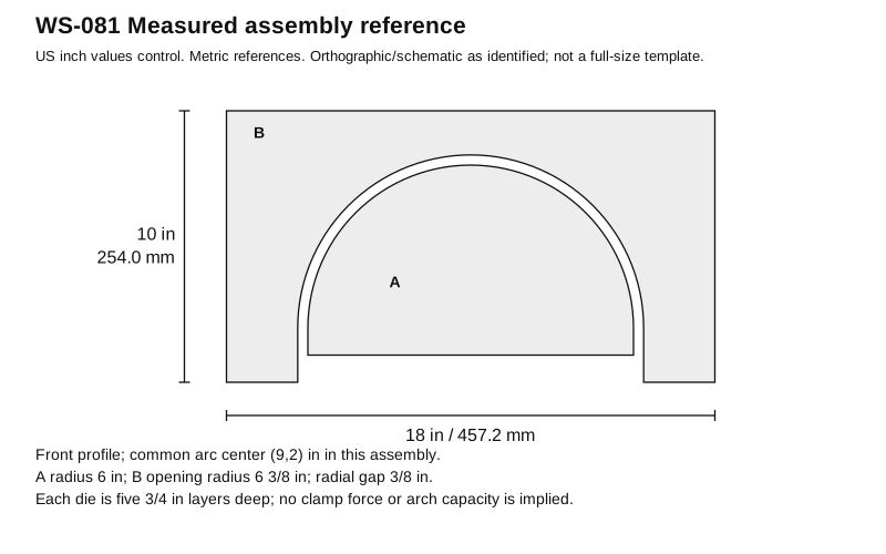
Place A inside B with male lower-left at female (3,1) in. Both arc centers are then (9,2) in; the radial gap is 6 3/8 minus 6 = 3/8 in. Check this at several angles before making any laminate.
Cut five C 20 x 3 1/2 x 1/16 in and dry-bend each gently around A under separate support. Stop for checking, short grain or a strip that needs excessive force; there is no steam vessel or heated bending process.
Wrap form contact faces in thin release film. Trial-fit the five strips with their ends free in the two vertical side gaps; 5 x 1/16 = 5/16 in wood leaves 1/16 in nominal allowance for films, adhesive and fit, so measure the actual full stack before gluing.
If the selected adhesive permits this cold lamination, coat strips per its instructions and nest the stack. Set three intact bar clamps vertically at female X=5,9,13 in, between B top and A bottom, using pads; close gradually by hand without forcing form legs together or exceeding maker instructions.
Keep the clamping/cure conditions required by the adhesive, then release clamps gradually, remove B and lift the arch. Measure actual springback and inspect the scrap bond; label it NONSTRUCTURAL TRIAL and do not use it for a load-bearing bow, beam or structure.
Measured assembly reference; dimensions and coordinates are defined in the numbered method.Component cuts and profile notes; dimensions are finished cut envelopes, not sheet nesting.
Acceptance and use checks
Male/female arc radii 6 and 6 3/8 in share one center in assembly, leaving 3/8 in radial space.
Each form depth is 5 x 3/4 = 3 3/4 in; strip width 3 1/2 in is fully supported.
Five 1/16 in lamellae total 5/16 in before adhesive/film; actual stack must fit without forcing.
Care
Remove release film and adhesive residue without gouging the arcs.
Store forms dry and inspect ply bonds; replace a split or delaminated form.
Primary context
Sources support general context; they do not endorse these original designs or certify dimensions/performance.
WW-S01 - OSHA - Hand and Power Tools, OSHA 3080. General tool inspection, proper tool selection and securing work. Not these original project dimensions or performance.
WW-S02 - USDA Forest Products Laboratory - Wood Handbook, Chapter 8: Fastenings. General wood-fastener behavior and the need to consider actual material and joint conditions. No rated load is derived for these builds.
Physical build trial: not performed. No load rating. Builder checks in this draft have not been claimed as completed physical tests.