Tape measure and steel rule; pencil and square; clamps
Saw suited to the stated wood stock; eye and hearing protection
Fine abrasive and a smooth sanding block
Drill/driver, scrap backing, drill bits and pilot bits matched to the stated joints
Reliable bubble level and square; compass or trammel for the marked circles
Calculator with degree-mode arctangent
Step-by-step assembly
Inspect sound stock and a stable work surface. In the drawings x runs left to right, y front to rear and z upward.
Measure actual stock before cutting; nominal board names are not finished cross sections. Match each part to its label and material in the cut schedule.
Mark each finished cut separately, leaving saw kerf outside the line. Label parts, target +/-1/16 in and ease all hand-contact edges.
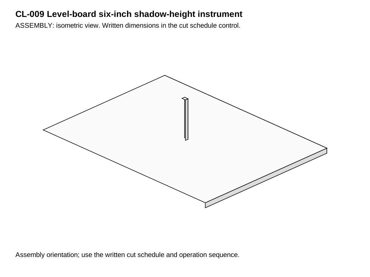
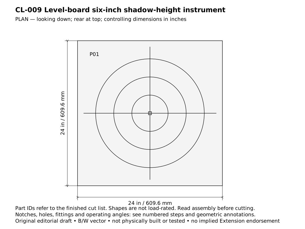
Cut the reference board to 24 x 24 in (2 x 2 ft). Check flatness with a straightedge in both diagonals. A cupped sheet cannot provide the horizontal reference; choose flat stock rather than trying to level a warped surface.
Mark the center at x=12, y=12 in. On the underside drill one 9/64 in screw clearance hole through the board. Mark the exact center of the 1/2 in square post end and pilot 3/32 in diameter, 5/8 in deep; first test the selected screw on a scrap of the same hardwood.
Seat the 6 in post directly on the board upper face and start the 1-1/4 in screw from below. With 3/4 in board thickness the remaining 1/2 in enters the post. Tighten gently; do not split the narrow end or leave a sharp point exposed.
Hold a reliable square against two adjacent post faces. Adjust to perpendicular before applying a small amount of suitable exterior glue at the post/base interface, then let cure without disturbing the post. Recheck the height from the BOARD TOP to the post top:6 in, not 6-3/4 in.
On the upper board draw two perpendicular centerlines through the post foot. Mark 1 in intervals outward in all four directions, labeling every second inch. Add concentric reference circles with radii 3, 6 and 9 in; these are shadow-length aids, not clock-hour lines.
Set the board on a stable surface in unobstructed sun. Use the level in two perpendicular directions and adjust with stable shims. Keep your eyes on the board; no sight tube, binocular, camera zoom or direct Sun viewing is needed.
Mark the middle of the shadow tip on the board and measure horizontal distance L from the post center. Record actual post height H and time/date. Compute elevation in degrees as arctan(H/L). With H=6 in: L=12 in gives 26.565 degrees, L=6 gives 45 degrees, L=3 gives 63.435 degrees.
If the shadow leaves the board, record an out-of-range result; do not invent a length. Repeat observations at safe daylight times to compare seasons and shade patterns. Local solar noon need not equal 12:00 on a clock. This instrument is an observation aid, not a survey, solar-array design or safety forecast.
Complete the listed acceptance checks before use. Record changes to stock or fittings; retain this sheet with the finished assembly.
Acceptance checks
Flat board 24 x 24 in (609.6 x 609.6 mm); post 6 in (152.4 mm) above its TOP surface.
Post perpendicular in two directions; board level in two directions before every reading.
A 6 in artificial shadow with a 6 in vertical test reference corresponds to a 45-degree right triangle.
Cleaning and maintenance
Protect from rain between sessions; recheck flatness, post height and plumb after storage or a knock.
Primary context
Primary references support context only. Design geometry, cut schedule, assembly and drawings are original editorial work, not certified or endorsed by the named agencies.