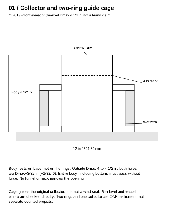
Construct an open direct-area liquid-rain collector with a transferred depth scale, a resettable wet zero and two removable-guide rings, then compare the rise of its meniscus over a stated observation interval.
Capacity. One original 6 1/2 in (165.1 mm) high collector, worked outside diameter 4 1/4 in (107.95 mm), on a 12 x 12 in (304.8 x 304.8 mm) base. Scale covers a 0 to 4 in (101.6 mm) rise above a 3/4 in (19.05 mm) initial wet-zero level. No official accuracy or storm capacity.
Local liquid-rain comparison only; not a flood warning, irrigation prescription, official reporting gauge, snow-water equivalent instrument or water supply. No physical catch, evaporation, leak, calibration-accuracy or weathering test has been performed.
Water-level rise equals rainfall depth only under the constant horizontal cross-section and level-opening assumptions. Wind, splash, obstructions, evaporation, wall wetting and handling can bias this homemade gauge. A comparison check does not establish meteorological accuracy.
The initial water must be restored to its actual wet-zero line BEFORE every interval. A level below zero is not negative rainfall; evaporation or leakage makes that interval indeterminate. An over-scale or overflowing interval is not a quantified total.
Do not leave water to freeze, store drinking water, attach a roof/downspout feed or deploy during hazardous weather. Remove before damaging wind, freezing conditions or unattended long storage. No universal network mounting height is claimed.
US customary actual inches; 12 in = 1 ft. Nominal stock labels are procurement descriptions. Reference millimeters = controlling inches x 25.4; do not recut from rounded conversions. Wood cuts +/-1/32 in; received wood thickness +/- .010 in. Collector dimensions and both guide-hole diameters are measured from the actual cylinder. This one design permits received outside diameter 4 to 4 1/2 in; the listed 4 1/4 in diameter is a worked example, not a brand claim or separate size variant.
P01 / Base - 1. 12 x 12 x 3/4 in / 304.80 x 304.80 x 19.05 mm. Exterior-bond plywood, actual 3/4 in. The collector rests directly on its top at Z .75; no hole or drainage route is cut under it. Clamp only outside the 8 x 8 in guide footprint.
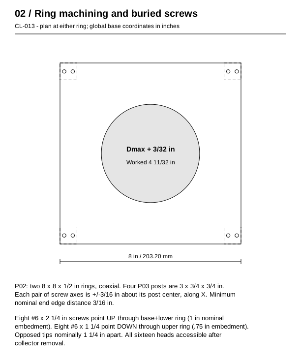
P02 / Matched guide rings - 2. 8 x 8 x 1/2 in / 203.20 x 203.20 x 12.70 mm. Exterior-bond plywood, actual 1/2 in. Global X/Y 2 to 10. Cut coaxial centered circular holes equal to measured maximum collector outside diameter Dmax plus 3/32 in, tolerance +1/32/-0. Worked Dmax 4.25 gives 4 11/32 in hole. Lower ring Z .75 to 1.25; upper Z 4.25 to 4.75.
P03 / Corner spacers - 4. 3 x 3/4 x 3/4 in / 76.20 x 19.05 x 19.05 mm. Sound straight wood, finished 3/4 in square. Vertical at X/Y 2 to 2.75 or 9.25 to 10; bottom Z 1.25, top 4.25. Two screw axes per end, local X +/-3/16 from center and local Y 0.
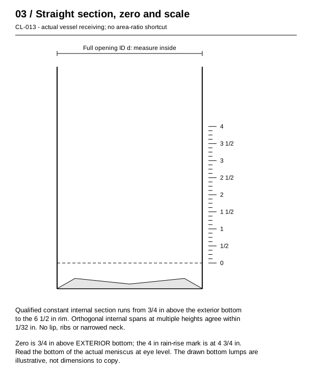
P04 / Original collector body - 1. 6 1/2 x 4 1/4 x 4 1/4 in / 165.10 x 107.95 x 107.95 mm. Sound transparent rigid plastic cylinder with intact closed bottom, cut from a suitable larger container; no glass. Height is cut 6.5 in; width/depth show worked OD 4.25 only. Receive full outside envelope 4 to 4.5 in without handles, neck, flare or bottom foot beyond Dmax. Constant round internal section must extend from 3/4 to 6 1/2 in above its exterior base. No spout, funnel or narrowed rim.
P05 / Waterproof depth-scale strip - 1. 6 x 1 x 0.005 in / 152.40 x 25.40 x 0.13 mm. Thin paper scale protected by clear waterproof tape; .005 in is illustrative thickness only. Transfer actual inch marks with a steel rule; zero at 3/4 in above collector exterior base, then 1/8 in ticks through 4 in rise. Label every 1/2 in; reference metric labels do not replace the inch baseline.
8 - #6 x 2 1/4 in stainless flat-head wood screws. Up through .75 in base and .5 in lower ring into 3 in spacers; nominal 1 in receiving penetration. Shaft OD<=.138, head OD<=.25 in.
8 - #6 x 1 1/4 in matching flat-head wood screws. Down through .5 in upper ring into spacers; nominal .75 in receiving penetration. Two per post; no ring screw enters the collector hole.
As needed - Water-resistant exterior wood coating and waterproof scale tape. Seal all wood faces/edges, cure before assembly. No tape, paint, adhesive bead or screen may overhang or narrow the collector opening.
4 - Separate low clamps matched to a stable support. Bodies remain wholly outside X/Y 2 to 10 and below the collector rim. Ground/low-bench mounting only; no rated wind retention.
1 - Separate accurate-enough rule and graduated water measure for comparison. A steel rule transfers the scale. A graduated mL measure checks equal-volume increments using ACTUAL opening ID; its resolution/accuracy limits the comparison and is not a calibration certificate.
Each interval - Plain clean reset water and a separate discard basin. Initial water establishes zero above bottom irregularities; it is not counted rainfall or potable storage. Discard after the observation and reset deliberately.
Rule, square, caliper and a long-reach inside caliper or sliding inside gauge; fine marker, scissors/snips appropriate to the container and abrasive for its cut edge.
Wood saw, supported jigsaw or hole-cutting tool for the large circular guide holes, clamps/backing scrap, drill/driver, 5/32 in clearances and trial 3/32 in receiving pilots with depth stop.
Level, straightedge, graduated water measure, two matched driver bits and eye protection. No glass cutting, powered rain sensor or pressure system.
01. Receive a transparent rigid plastic container before cutting the guide rings. It must stand flat on its intact bottom, have no handle or projecting foot, and provide at least 6 1/2 in height after the neck is removed. Its full outside diameter is 4 to 4 1/2 in. The internal section must be straight and round from the future 3/4 in zero height through 6 1/2 in; reject taper, ribs, a lip narrowing the mouth, cracks or an inaccessible interior.
02. On the empty vessel measure two perpendicular inside spans at the intended opening and at several levels down the straight section using a long-reach inside gauge. All spans must agree within 1/32 in; record the actual mean opening ID d and maximum outside diameter Dmax over the WHOLE 6 1/2 in body, including its bottom. A catalog volume or outside diameter is not its catch area. Do not flatten a tapered bottle to pass this check.
03. Wrap a paper cutting guide at 6 1/2 in above the exterior bottom. Cut off the top with supported suitable snips or a fine saw, without puncturing the retained wall. Ease its edge without a folded lip. Check four rim points: height variation<=1/32 in on a level base. No neck, funnel, tape-overhang or thick inward bead remains. The opening and water column must have the same qualified area.
04. Cut P01-P03, leaving 1/8 in kerf between separate finished blanks. Stack and clamp the two 8 in square rings with matching orientation marks. At their center 4, 4 in mark a circle of diameter Dmax+3/32 in; cut both over backing and finish without enlarging more than 1/32. Worked Dmax 4 1/4 gives 4 11/32 in. Verify the complete empty container passes through both, including its bottom, without force.
05. Mark two screw axes per corner spacer. Global post centers are (2 3/8, 2 3/8), (9 5/8, 2 3/8), (2 3/8, 9 5/8), (9 5/8, 9 5/8). Each pair is at center X +/-3/16, same Y. Thus every axis has 3/16 in nominal edge distance in the .75 in post; no oversized countersink is permitted in a post end.
06. Clamp the lower ring on the base at X/Y 2 to 10, with the 4 in local center at global 6, 6. Set all four 3 in spacers on its corners at Z 1 1/4 to 4 1/4. Match-drill 5/32 in clearance through base and lower ring; trial 3/32 in pilots into actual end grain. Full receiving cylinder 1 1/16 in plus point<=.040 and 1/32 reserve gives total<=1 3/16 in, covering the worst received first-member thickness. Drive the eight 2 1/4 in screws upward, heads flush under the base; keep the ring flat.
07. Set the upper ring on the four spacer tops at Z 4 1/4 to 4 3/4, aligned with the lower ring orientation marks. Check the complete container passes both holes vertically before fastening. Make 5/32 in first-member clearances and trial 3/32 pilots in each post top: .8125 in full cylinder plus point<=.040 and 1/32 reserve, total<=15/16 in, covering worst received embedment. Fit eight 1 1/4 in screws downward. Their tips remain at least 1 1/4 in above the lower screw tips at nominal dimensions.
08. Remove the vessel; seal the wood faces and hole edges, observing coating cure instructions. Recheck that neither ring grips the container. The guide holes locate it laterally but are not weather seals or a wind-rated clamp. Set the container bottom flat on the base at global center 6, 6. Check vertical wall and horizontal rim in two perpendicular directions with the actual vessel seated.
09. Make the 1 x 6 in scale strip. From a bottom reference draw zero 3/4 in above the EXTERIOR bottom, then transfer thirty-two 1/8 in intervals up to the 4 in mark. Label 0, 1/2, 1, 1 1/2, 2, 2 1/2, 3, 3 1/2 and 4. At the 4 in mark the height is 4 3/4 in above the exterior bottom, not 4 in. Cover the strip fully with clear tape outside the vessel, below its rim; verify zero and 4 in marks against the steel rule AFTER taping.
10. Fill plain water to the zero line with the vessel installed and level. Read the BOTTOM of the meniscus at eye level; avoid a slant view through curved plastic. The zero water must cover every internal bottom irregularity yet remain inside the verified straight section. If the listed 3/4 in zero cannot do both, reject that container rather than inventing a new baseline for this guide.
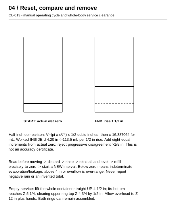
11. Perform an equal-volume comparison before outdoor use. For actual opening ID d in inches, area A=pi*d*d/4 square inches; a 1/2 in depth rise requires V=A*0.5 cubic inches, or V*16.387064 mL. For the worked INTERNAL d=4.20 in, each 1/2 in increment is 113.5 mL; outside Dmax 4.25 is not d. Starting at zero, add eight equal increments and compare the meniscus at each half-inch mark through 4 in. Stop for progressive disagreement greater than 1/8 in, leakage or an ambiguous meniscus. This broad check includes the water-measure errors and does not prove 1/8 in weather accuracy.
12. Before field use, place the bare collector on fresh dry absorbent paper inside a separate shallow tray indoors. Fill it to the 4 in scale mark, wipe away exterior splashes, note the meniscus and leave it undisturbed for 30 minutes. Inspect for new dampness at the base/wall and any visible level drop; unexplained dampness or drop rejects the vessel. This is a short receiving observation, not a leak or evaporation certificate. Empty into the discard basin, rinse, reinstall on the same orientation mark and refill precisely to actual zero. Do not use a guessed initial volume as that setting.
13. Clamp the full base to a stable low support, with all clamp bodies outside the 8 in square guide footprint and below the rim. Level the base and then check the actual opening itself. Do not put a tall object, overhang, board edge or plant directly above or alongside the mouth. Avoid sprinklers, roof runoff, splash from paving and visibly turbulent sites. This original low instrument has no network-compliant mounting height.
14. Record the interval start only AFTER verifying the initial meniscus at zero, vessel plumb, clear opening and fixed orientation. Choose a consistent daily or event interval that can be read safely; record its actual times. Do not add reset water during the interval or move the gauge to improve a reading. Use official warnings separately; never go outdoors into dangerous weather to preserve a measurement.
15. At the end read at eye level before moving the vessel. The scale rise above zero is the comparison rainfall depth only under the stated uniform-area/level assumptions. Read no finer than the 1/8 in marks; record an unresolved trace instead of a false precise number. A below-zero level indicates evaporation/leakage, not negative rain. Wind, evaporation during rain, splashes or an altered start level are uncorrected uncertainties.
16. If water exceeds the 4 in mark, record over-range, not a quantified total; an overflow loses information. Do not subtract an unmeasured amount or sum an interrupted interval unless every emptying was actually measured and documented. For this simple worked procedure, end that interval and reset for a separate one when safe. Do not use frozen or partly melted contents as a rain-only reading.
17. For routine service note the final reading first, then lift the vessel STRAIGHT UP at least 4 1/2 in so its entire bottom clears the upper ring; allow overhead to at least Z 12 in plus hands. Collect no water through the wood holes. Empty/rinse the vessel separately and inspect scale adhesion, cut rim and bottom. With the vessel out, all eight upper-ring screw heads are accessible if deeper cage cleaning is needed.
18. Dry the assembly for storage and leave no long-standing reset water. Refit the same rings/posts and fastener order if opened; do not change the hole/collector fit silently. After any vessel replacement, coating build-up, knock or scale shift, repeat full-body pass, rim/plumb, zero/rule, equal-volume and leak checks. Begin the next interval only after a fresh actual zero. No certified catch or calibration claim is made.
Full original collector 6 1/2 in high; complete outside body passes both actual holes; no neck, internal narrowing, taper, loose rim or handle.
Recorded inside spans agree within 1/32 in over the qualified straight section; rim height variation<=1/32 in. Actual catch opening equals the water-column section by receiving inspection.
Sixteen wood screws stay inside their intended stock; ring holes coaxial, vessel stands flat, rim horizontal and wall plumb in two directions.
Actual wet zero 3/4 in above exterior bottom covers all irregularities; scale 4 in rise is at 4 3/4 in above that bottom. Meniscus read at eye level.
Equal-volume half-inch comparison and leak receiving checks completed with actual d and separate water measure; no official calibration claim.
Reset before each interval; below-zero, over-range, freezing, disturbed or compromised intervals are identified as indeterminate rather than fabricated totals.
Empty after each observation. Rinse and air-dry vessel and rings; inspect for trapped debris, insects, cracks, scale lift or changed rim. Do not store water outdoors between intended observations.
Keep all coating/tape outside the opening. Recheck actual plumb, wet zero and scale after every reset; repeat full comparison checks after replacement or damage.
Original geometry, instructions and vector plates. Primary sources supply instrument or material context; they do not endorse or certify this apparatus.
NOAA JetStream: It is the Rain, Man. Straight-sided collector and ruler/reset context; this original wet-zero cage design and its accuracy limits are separate.
National Weather Service Albuquerque: Instrument Siting. Obstruction and wind/turbulence exposure affect catch. Network-specific siting is not claimed for this original low instrument.