Garden · GA-041
Three-four-five garden layout square
Transfer a right-angle layout to garden paths and bed corners using a rigid 36 × 48 in reference.
Editorial construction draft. Original digital diagrams; no physical build or load certification. Read dimensions, fit and use limits before making changes. US customary dimensions control; metric values are references.
Before marking and cutting
- Measure the stated stock sections before cutting. Use the cut-list geometry, not scale measurements from the drawing.
- US inch dimensions control; millimeter values are rounded conversions. Ordinary cut target ±1/16 in (1.6 mm); fit commercial accessories before boring attachment holes.
Use limits
- Original bounded garden component, not an occupied structure.
- No human standing, sitting, climbing, lifting or fall protection use. No stated safe working load.
- Geometry and fastener quantities are editorially checked; no prototype build, wind test or crop trial is claimed.
Materials and cuts
| Part | Qty | Size to cut | Material |
|---|---|---|---|
| P01 Short arm | 1 | 36 × 2 1/2 × 3/4 in 914.4 × 63.5 × 19.05 mm | 1 × 3 in board sound untreated cedar or other durable untreated wood |
| P02 Long arm extension | 1 | 45 1/2 × 2 1/2 × 3/4 in 1155.7 × 63.5 × 19.05 mm | 1 × 3 in board sound untreated cedar or other durable untreated wood |
| P03 Corner gusset | 1 | 8 × 8 × 3/4 in 203.2 × 203.2 × 19.05 mm | measured 3/4 in plywood exterior-bond plywood for protected non-food-contact fixtures |
Hardware and consumables
- 8 #8 × 1-1/4 in screws for gusset: 4 into each arm
- Wood glue; 60 in steel tape for diagonal verification
Tools
- Tape measure and steel rule
- Pencil, square and clamps
- Saw suited to the stated stock; eye and hearing protection
- Drill/driver, countersink and bits matched to fasteners
- Sandpaper and edge file; gloves when handling cut mesh
Assembly
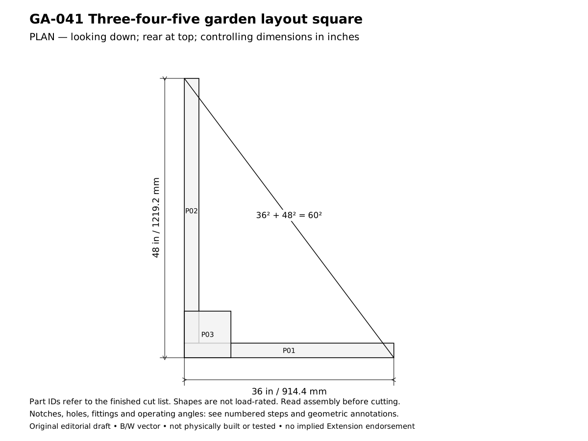
- Plan the three-four-five garden layout square for this result: Transfer a right-angle layout to garden paths and bed corners using a rigid 36 × 48 in reference. Confirm the design reference before cutting: Outside reference legs 36 and 48 in; diagonal 60 in within the reading accuracy of the tape. In the drawings x runs left to right, y runs front to rear and z runs upward.
- Verify the required stock before laying out these parts: 1 × 3 in board: actual 0.75 × 2.5 in (19.05 × 63.5 mm); measured 3/4 in plywood: measured thickness 0.75 in. Reject split or twisted wood and unknown salvage; thinner stock requires recalculating the joints, not simply using the listed lengths.
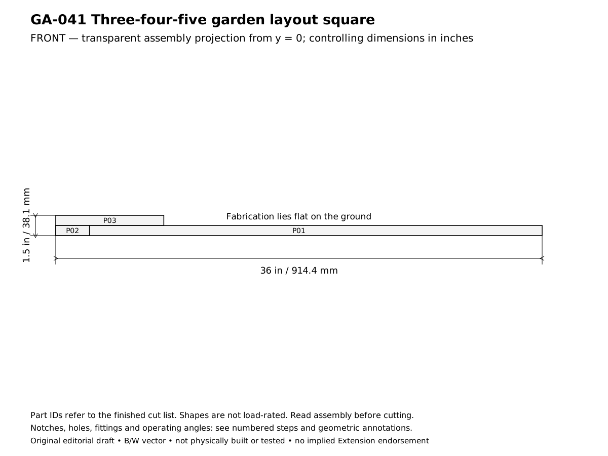
- Cut and label the finished parts: 1 Short arm 36 × 2.5 × 0.75 in (914.4 × 63.5 × 19.05 mm), mark P01; 1 Long arm extension 45.5 × 2.5 × 0.75 in (1155.7 × 63.5 × 19.05 mm), mark P02; 1 Corner gusset 8 × 8 × 0.75 in (203.2 × 203.2 × 19.05 mm), mark P03. Keep saw kerf outside each finished line. Rip only where the finished width is narrower than the actual stock; use a suitable guide and target ±1/16 in (1.6 mm) for ordinary cuts. Dowel triples mean length × diameter × diameter, not square dowel stock.
- Lay the short arm along x = 0–36 in and long extension along y = 2-1/2–48 in with its end against the short arm. The outer reference legs are 36 and 48 in.
- Place the 8 × 8 in gusset over the inside corner. Mark four screw centers above each arm, away from the common butt joint.
- Clamp the two arms to a flat bench with their outside edges against straight fences. Leave the gusset loose while checking the geometry.
- Measure from the short-arm outside end at (36,0) to the long-arm outside end at (0,48). Adjust until the diagonal is 60 in (1524 mm).
- Apply glue only over the arm-contact areas beneath the gusset. Re-clamp, recheck 36/48/60 in and drill the eight pilots.
- Drive eight 1-1/4 in screws through the gusset into the arms, with tips buried. Do not move the assembly until the glue cures.
- Label the two outside edges REFERENCE and mark a witness line across the arm/gusset joints so later movement is visible.
- Use on the ground to mark one corner at a time, checking the longer site diagonals separately. Do not use as a ladder, survey instrument or structural bracing.
- Complete the acceptance checks below before putting the assembly into service. Record any changed stock thickness, fastener or equipment fit on the project sheet. The published geometry has not been physically built or load-tested.
Checks
- Outside reference legs 36 and 48 in; diagonal 60 in within the reading accuracy of the tape.
- Arms lie flat and witness lines remain continuous after gentle handling.
Operation
- A garden layout aid, not a legal boundary or construction survey.
Cleaning and maintenance
- Store flat under cover and recheck the diagonal before each layout.
Primary context
These sources inform the context and do not endorse the original construction design.