Garden · GA-054
Removable nonpotable-reservoir screen cap
Hold a fine insect-screen sheet over a compatible sound reservoir opening while preserving the reservoir’s separate overflow route.
Editorial construction draft. Original digital diagrams; no physical build or load certification. Read dimensions, fit and use limits before making changes. US customary dimensions control; metric values are references.
Before marking and cutting
- Measure the stated stock sections before cutting. Use the cut-list geometry, not scale measurements from the drawing.
- US inch dimensions control; millimeter values are rounded conversions. Ordinary cut target ±1/16 in (1.6 mm); fit commercial accessories before boring attachment holes.
Use limits
- Original bounded garden component, not an occupied structure.
- No human standing, sitting, climbing, lifting or fall protection use. No stated safe working load.
- Geometry and fastener quantities are editorially checked; no prototype build, wind test or crop trial is claimed.
Materials and cuts
| Part | Qty | Size to cut | Material |
|---|---|---|---|
| P01 Long cap rails | 2 | 14 × 1 1/2 × 3/4 in 355.6 × 38.1 × 19.05 mm | 1 × 2 in board sound untreated cedar or other durable untreated wood; no unknown salvage |
| P02 End cap rails | 2 | 11 × 1 1/2 × 3/4 in 279.4 × 38.1 × 19.05 mm | 1 × 2 in board sound untreated cedar or other durable untreated wood; no unknown salvage |
| P03 Screen panel | 1 | 14 × 14 × 1/25 in 355.6 × 355.6 × 1.02 mm | insect mesh UV-resistant synthetic screening; not a food-contact certification |
| P04 Cover strips | 2 | 14 × 1 1/2 × 3/4 in 355.6 × 38.1 × 19.05 mm | 1 × 2 in board sound untreated cedar or other durable untreated wood; no unknown salvage |
Hardware and consumables
- 8 #8 × 2-1/2 in screws for flat cap-frame butt corners
- 12 #8 × 1-1/4 in screws for cover strips
- 2 smooth removable edge channels, 14 in each
- Positive cap hold-down compatible with the reservoir; no reliance on gravity alone
Tools
- Tape measure and steel rule
- Pencil, square and clamps
- Saw suited to the stated stock; eye and hearing protection
- Drill/driver, countersink and bits matched to fasteners
- Sandpaper and edge file; gloves when handling cut mesh
Assembly
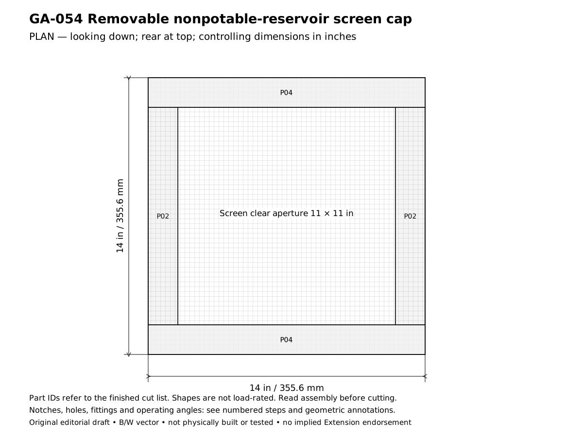
- Plan the removable nonpotable-reservoir screen cap for this result: Hold a fine insect-screen sheet over a compatible sound reservoir opening while preserving the reservoir’s separate overflow route. Confirm the design reference before cutting: Cap bears continuously on sound rim; positive hold-down fitted and no open edge gaps. In the drawings x runs left to right, y runs front to rear and z runs upward.
- Verify the required stock before laying out these parts: 1 × 2 in board: actual 0.75 × 1.5 in (19.05 × 38.1 mm); insect mesh: UV-resistant synthetic screening; not a food-contact certification. Reject split or twisted wood and unknown salvage; thinner stock requires recalculating the joints, not simply using the listed lengths.
- Cut and label the finished parts: 2 Long cap rails 14 × 1.5 × 0.75 in (355.6 × 38.1 × 19.05 mm), mark P01; 2 End cap rails 11 × 1.5 × 0.75 in (279.4 × 38.1 × 19.05 mm), mark P02; 1 Screen panel 14 × 14 × 0.04 in (355.6 × 355.6 × 1.02 mm), mark P03; 2 Cover strips 14 × 1.5 × 0.75 in (355.6 × 38.1 × 19.05 mm), mark P04. Keep saw kerf outside each finished line. Rip only where the finished width is narrower than the actual stock; use a suitable guide and target ±1/16 in (1.6 mm) for ordinary cuts. Dowel triples mean length × diameter × diameter, not square dowel stock.
- Confirm the actual reservoir has a sound continuous rim that supports the 14 in cap and an independent overflow. The example clear frame opening is 11 × 11 in.
- Assemble the 14 × 14 in frame flat, with 11 in end rails between long rails. Pilot through each 1-1/2 in-wide long rail into the end-rail end and use two #8 × 2-1/2 in screws per corner, centered in the 3/4 in thickness. Keep the top plane flat.
- Cut the screen to 14 × 14 in and stretch it gently across the upper face. Do not make it drum-tight or leave sagging pockets that collect water.
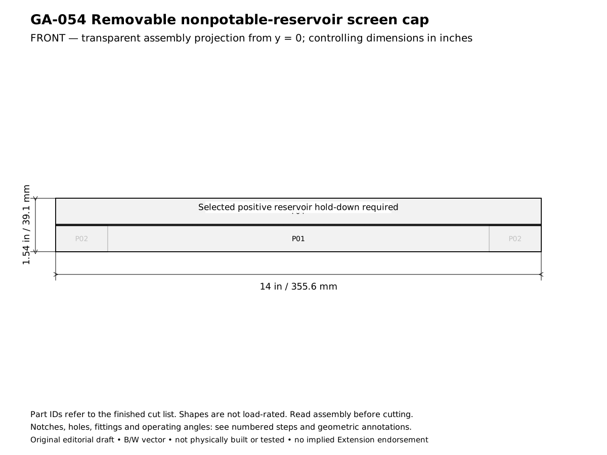
- Clamp the two 14 in cover strips above front/rear rails. Use six vertical screws per strip at x = 3/4, 3-1/4, 5-3/4, 8-1/4, 10-3/4 and 13-1/4 in, centered across the rail width. These x positions avoid the horizontal corner-screw paths; keep tips in the combined wood stack.
- Trap the remaining two screen edges in smooth removable edge channels fitted to the screen thickness. No sharp or loose edge may project over the opening.
- Test-fit on the actual rim without blocking inlet or overflow. Add a positive compatible hold-down so children, pets, wind or handling cannot dislodge it.
- Pour a small controlled amount of clean test water onto the empty screen outdoors and confirm drainage into the reservoir, while the independent overflow stays unobstructed.
- Label the reservoir NONPOTABLE. Screen exclusion is limited by real mesh, gaps and maintenance; it does not disinfect roof water, make it drinkable or replace a safe reservoir lid/child-protection design.
- Complete the acceptance checks below before putting the assembly into service. Record any changed stock thickness, fastener or equipment fit on the project sheet. The published geometry has not been physically built or load-tested.
Checks
- Cap bears continuously on sound rim; positive hold-down fitted and no open edge gaps.
- No standing-water pocket on screen; overflow remains separate and open.
Operation
- Only for a suitably enclosed nonpotable reservoir; never leave an open tank accessible to children.
- Use roof water on appropriate inedible landscape plants, not drinking/cooking/produce washing.
Cleaning and maintenance
- Remove leaves after rain, inspect gaps and replace damaged screen promptly.
Primary context
These sources inform the context and do not endorse the original construction design.