Garden · GA-055
Ground-level downspout debris catcher
Catch large roof leaves in a removable screened tray below an existing ground-level discharge, with a clear bypass around the tray.
Editorial construction draft. Original digital diagrams; no physical build or load certification. Read dimensions, fit and use limits before making changes. US customary dimensions control; metric values are references.
Before marking and cutting
- Measure the stated stock sections before cutting. Use the cut-list geometry, not scale measurements from the drawing.
- US inch dimensions control; millimeter values are rounded conversions. Ordinary cut target ±1/16 in (1.6 mm); fit commercial accessories before boring attachment holes.
Use limits
- Original bounded garden component, not an occupied structure.
- No human standing, sitting, climbing, lifting or fall protection use. No stated safe working load.
- Geometry and fastener quantities are editorially checked; no prototype build, wind test or crop trial is claimed.
Materials and cuts
| Part | Qty | Size to cut | Material |
|---|---|---|---|
| P01 Long rails | 2 | 18 × 2 1/2 × 3/4 in 457.2 × 63.5 × 19.05 mm | 1 × 3 in board sound untreated cedar or other durable untreated wood |
| P02 End rails | 2 | 10 1/2 × 2 1/2 × 3/4 in 266.7 × 63.5 × 19.05 mm | 1 × 3 in board sound untreated cedar or other durable untreated wood |
| P03 Mesh floor | 1 | 18 × 12 × 1/25 in 457.2 × 304.8 × 1.02 mm | galvanized hardware cloth 1/4 in grid, about 19 gauge; all cut edges trapped under battens; soil contact only |
| P04 Lower battens | 2 | 18 × 1 1/2 × 3/4 in 457.2 × 38.1 × 19.05 mm | 1 × 2 in board sound untreated cedar or other durable untreated wood; no unknown salvage |
| P05 Drain clearance runners | 2 | 12 × 1 1/2 × 1 1/2 in 304.8 × 38.1 × 38.1 mm | 2 × 2 in board sound untreated wood |
Hardware and consumables
- 8 #8 × 1-1/2 in screws for corners
- 12 #8 × 1-1/4 in screws for battens
- 2 smooth 12 in edge channels for remaining wire edges
- Existing engineered/site-appropriate drainage route; not supplied by this fixture
- 4 #8 × 2 in screws upward through drain runners into lower battens, one per crossing
Tools
- Tape measure and steel rule
- Pencil, square and clamps
- Saw suited to the stated stock; eye and hearing protection
- Drill/driver, countersink and bits matched to fasteners
- Sandpaper and edge file; gloves when handling cut mesh
Assembly
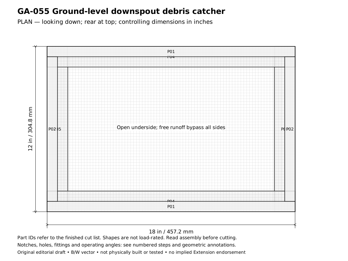
- Plan the ground-level downspout debris catcher for this result: Catch large roof leaves in a removable screened tray below an existing ground-level discharge, with a clear bypass around the tray. Confirm the design reference before cutting: No exposed mesh edges; tray can be lifted without touching the discharge. In the drawings x runs left to right, y runs front to rear and z runs upward.
- Verify the required stock before laying out these parts: 1 × 2 in board: actual 0.75 × 1.5 in (19.05 × 38.1 mm); 1 × 3 in board: actual 0.75 × 2.5 in (19.05 × 63.5 mm); galvanized hardware cloth: 1/4 in grid, about 19 gauge; all cut edges trapped under battens; soil contact only; 2 × 2 in board: actual 1.5 × 1.5 in (38.1 × 38.1 mm). Reject split or twisted wood and unknown salvage; thinner stock requires recalculating the joints, not simply using the listed lengths.
- Cut and label the finished parts: 2 Long rails 18 × 2.5 × 0.75 in (457.2 × 63.5 × 19.05 mm), mark P01; 2 End rails 10.5 × 2.5 × 0.75 in (266.7 × 63.5 × 19.05 mm), mark P02; 1 Mesh floor 18 × 12 × 0.04 in (457.2 × 304.8 × 1.02 mm), mark P03; 2 Lower battens 18 × 1.5 × 0.75 in (457.2 × 38.1 × 19.05 mm), mark P04; 2 Drain clearance runners 12 × 1.5 × 1.5 in (304.8 × 38.1 × 38.1 mm), mark P05. Keep saw kerf outside each finished line. Rip only where the finished width is narrower than the actual stock; use a suitable guide and target ±1/16 in (1.6 mm) for ordinary cuts. Dowel triples mean length × diameter × diameter, not square dowel stock.
- Assemble the 18 × 12 in open frame with the 10-1/2 in end rails between the long rails. Fasten two screws per corner.
- Clamp the frame square before final tightening. The clear aperture is 16-1/2 × 10-1/2 in.
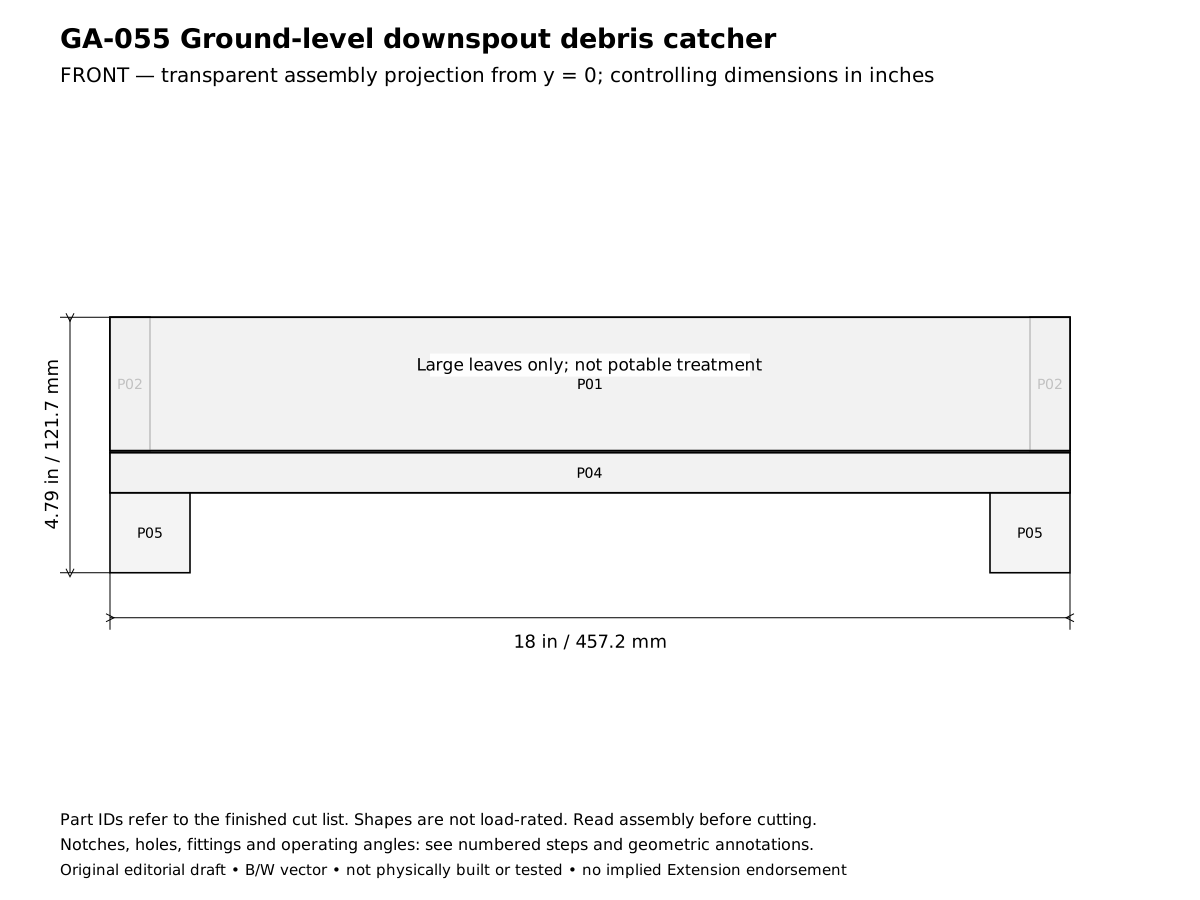
- Lay the 18 × 12 in mesh beneath it and trap front/rear edges with the two battens, six screws per batten.
- Crimp smooth edge channels over the two remaining mesh edges. File burrs and verify no wire can contact a hand during lifting.
- Choose an existing ground-level downspout outlet whose drainage route is already suitable. Do not modify roof gutters, create a blockage in a pipe or direct runoff toward foundations.
- Fit the two 12 in runners beneath the battens at x = 0–1-1/2 and 16-1/2–18 in. From beneath each runner drill/drive one #8 × 2 in screw at y = 3/4 and 11-1/4 in into the batten above, four total; tips stop inside the batten. Place on the existing suitable splash area with all runoff bypass paths clear.
- Run a small low-flow test while watching the entire bypass. Remove the catcher immediately if water backs up or leaves carry flow toward a structure.
- Lift and empty after each event. This coarse catcher intercepts leaves only; it does not remove pathogens, chemicals or sediment fine enough to pass the mesh.
- Complete the acceptance checks below before putting the assembly into service. Record any changed stock thickness, fastener or equipment fit on the project sheet. The published geometry has not been physically built or load-tested.
Checks
- No exposed mesh edges; tray can be lifted without touching the discharge.
- Independent runoff bypass stays clear even if the mesh is fully covered with leaves.
Operation
- Not a potable prefilter or a drainage design. Keep away from roof-height work and foundation outlets without a verified route.
Cleaning and maintenance
- Clear debris promptly and remove in freezing weather if ice could obstruct drainage.
Primary context
These sources inform the context and do not endorse the original construction design.