Build a small complete cabinet component whose shelf can be removed and repositioned without taking apart the carcass.
Original bounded component build. Dimensions describe this example, not an approved structural, occupied-building or universal fit design. Unbuilt / untested. US customary dimensions control.
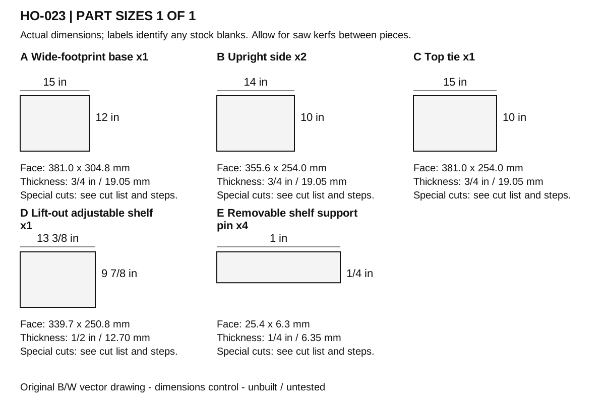
| Part | Quantity | Actual dimensions | Material / special cut |
|---|---|---|---|
| A Wide-footprint base | 1 | 15 in x 12 in x 3/4 in 381.0 x 304.8 x 19.05 mm | Sound untreated hardwood or exterior-bond plywood, actual measured thickness; reject split/warped stock Square ends; remove all splinters and burrs. |
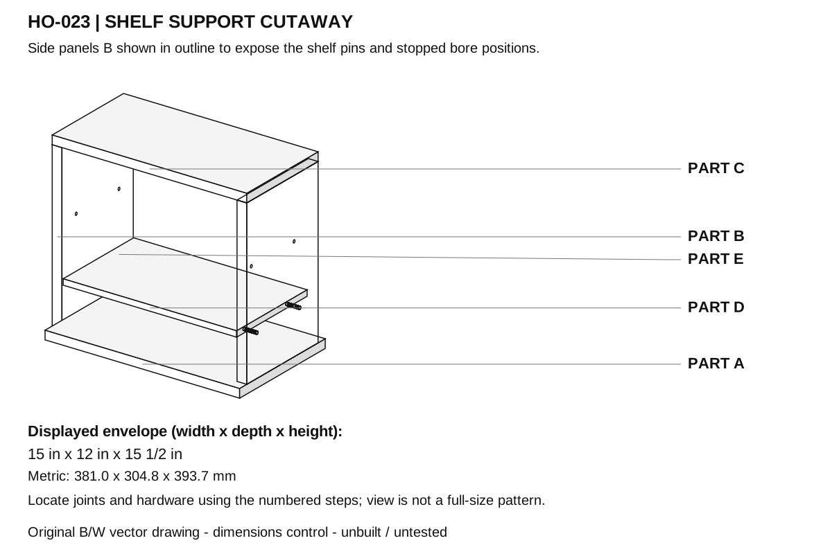
| B Upright side | 2 | 14 in x 10 in x 3/4 in 355.6 x 254.0 x 19.05 mm | Sound untreated hardwood or exterior-bond plywood, actual measured thickness; reject split/warped stock Inside-face pin bores: 1/4 in diameter,1/2 in stopped depth; center rows 3 1/4 and 8 1/4 in above side bottom,2 and 8 in from its front edge. |
| C Top tie | 1 | 15 in x 10 in x 3/4 in 381.0 x 254.0 x 19.05 mm | Sound untreated hardwood or exterior-bond plywood, actual measured thickness; reject split/warped stock Square ends; remove all splinters and burrs. |
| D Lift-out adjustable shelf | 1 | 13 3/8 in x 9 7/8 in x 1/2 in 339.725 x 250.825 x 12.7 mm | Sound untreated hardwood or exterior-bond plywood, actual measured thickness; reject split/warped stock Square ends; remove all splinters and burrs. |
| E Removable shelf support pin | 4 | 1 in x 1/4 in x 1/4 in 25.4 x 6.35 x 6.35 mm | Straight 1/4 in round hardwood dowel; actual diameter verified in trial bores Round ends without shortening the 1 in overall length. Mark insertion depth 7/16 in from one end. |
Tape, square, pencil; clamped saw setup appropriate to the material; drill/driver and depth stop; countersink for wood fasteners; files/sanding block; clamps. Specific additional tools are noted in the steps.
x=left/right, y=front/rear, z=up; origin is front-left underside unless stated
Retained segments with the same part/instance belong to one machined stock piece, not additional parts. Positions and sizes below are US inches; rotations are degrees.
| Part / instance | Origin x,y,z | Size / rotation |
|---|---|---|
| A / 1 | [0, 0, 0] | [15, 12, 0.75] / [0, 0, 0] |
| B / 1 | [0, 1, 0.75] | [0.75, 10, 14] / [0, 0, 0] |
| B / 2 | [14.25, 1, 0.75] | [0.75, 10, 14] / [0, 0, 0] |
| C / 1 | [0, 1, 14.75] | [15, 10, 0.75] / [0, 0, 0] |
| D / 1 | [0.8125, 1.0625, 4.125] | [13.375, 9.875, 0.5] / [0, 0, 0] |
| E / 1 | [0.3125, 2.875, 3.875] | [1, 0.25, 0.25] / [0, 0, 0] |
| E / 2 | [0.3125, 8.875, 3.875] | [1, 0.25, 0.25] / [0, 0, 0] |
| E / 3 | [13.6875, 2.875, 3.875] | [1, 0.25, 0.25] / [0, 0, 0] |
| E / 4 | [13.6875, 8.875, 3.875] | [1, 0.25, 0.25] / [0, 0, 0] |
No seating, stepping, climbing, child-access installation or stored-load capacity is supplied.
Do not glue the removable pins in place, deepen the bores through the outer face or add an unassessed wall mount.
Empty the shelf before inspecting it. Check the sixteen carcass screws, side-bore edges and all four pins for looseness, cracks or crushed fibers; stop at racking or a rocking shelf.
Remove the shelf and pins to brush dust from their bearing faces. Use the actual wood or finish supplier cleaning method; do not soak the stopped bores or leave moisture inside them. Dry fully before replacing the pins.
After a humidity change repeat the empty fit and four-point contact check at the selected level. Replace a damaged pin or split side rather than driving a larger pin into an unassessed bore. No stored-load or anchorage rating is established.
Purdue University Extension: Wood drying: FNR-37 Source
American Wood Council: 2021 Code Conforming Wood Design, wall-framing context Source