Open a complete framed insect screen by hand for attended utility access, then let two intact factory spring hinges return the sash against its overlapping rear stops.
Original authored guide. Unbuilt and untested. HO-038
One small sheltered dry utility-opening component, not a personnel door, escape/rescue opening, fall barrier, child/pet guard, fire door, weather window, security device or predator barrier. Never fit it to required egress or an opening occupied by a person.
The spring hinge is a bought intact mechanism; no spring pin is removed or spring modified. The original design covers a supported 0..90 degree outward sweep only. Hold the sash while opening; do not force the factory hinge beyond that range. Closing is not damped and no closing-speed or pinch-protection claim is made.
Actual screen condition, overlap and seating are inspected before use. A returned sash does not establish insect exclusion, airflow, weather resistance or a code rating. No construction, closing, insect, wind or durability trial has been performed.
US customary actual inches control original wood geometry; reference millimeters equal inches x 25.4. Retain exact metric catalog dimensions for unmodified factory hardware and transfer actual holes rather than recutting a rounded inch conversion.
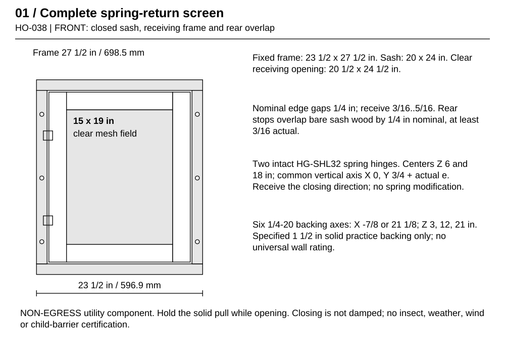
Ordinary wood lengths +/-1/32 in, actual 3/4 and 1/4 in gauges +/-0.010 in. Set the actual closed perimeter clearance to 3/16..5/16 in and the rear overlap to at least 3/16 in. Every bearing face is flat. Critical bores, counterbores and metal trimming use the explicit receiving limits below; do not use general cut tolerance to waive a failed fitted clearance. At the hinge line receive bare wood edges X<=-1/8 and X>=+1/8, with hinge-side gap 1/4..5/16 in; the other perimeter gaps remain 3/16..5/16.
A / Fixed full-width rail / quantity 2. 23 1/2 x 3/4 x 1 1/2 in (596.9 x 19.05 x 38.1 mm). Sound straight untreated wood, finished to the listed ACTUAL dimensions; no nominal-size substitution. X length; lower Z -1 5/8..-1/8, upper Z 24 3/8..25 7/8; X -1 5/8..21 7/8, Y 0..3/4.
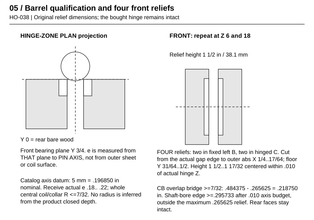
B / Fixed between-rail stile / quantity 2. 1 1/2 x 3/4 x 24 1/2 in (38.1 x 19.05 x 622.3 mm). Sound straight untreated wood, finished to the listed ACTUAL dimensions; no nominal-size substitution. X -1 5/8..-1/8 and 20 3/8..21 7/8; Z -1/8..24 3/8. Frame outside 23 1/2 x 27 1/2, clear opening 20 1/2 x 24 1/2 in. The HINGE-SIDE member only has two local front edge reliefs: Z 6 or 18 +/-3/4, from its actual inner gap edge to X -1/4(B) or+1/4(C), Y 1/2..3/4 only. Nominal 1/8 wide x 1/4 deep x 1 1/2 high; receive floor Y 31/64..1/2 and outer abs X 1/4..17/64; rear face remains intact.
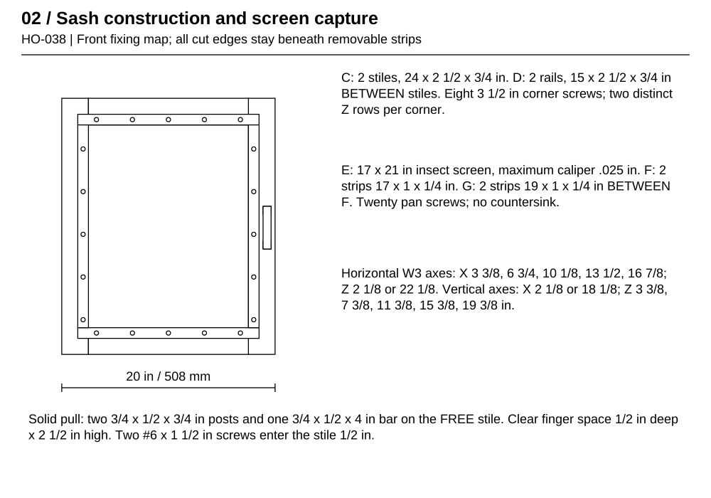
C / Full-height sash stile / quantity 2. 2 1/2 x 3/4 x 24 in (63.5 x 19.05 x 609.6 mm). Sound straight untreated wood, finished to the listed ACTUAL dimensions; no nominal-size substitution. Closed left X 1/8..2 5/8, right 17 5/8..20 1/8; Z 1/8..24 1/8. Leave the outer 1 1/2 in of the hinged stile free of screening and battens. The HINGE-SIDE member only has two local front edge reliefs: Z 6 or 18 +/-3/4, from its actual inner gap edge to X -1/4(B) or+1/4(C), Y 1/2..3/4 only. Nominal 1/8 wide x 1/4 deep x 1 1/2 high; receive floor Y 31/64..1/2 and outer abs X 1/4..17/64; rear face remains intact.
D / Between-stile sash rail / quantity 2. 15 x 3/4 x 2 1/2 in (381.0 x 19.05 x 63.5 mm). Sound straight untreated wood, finished to the listed ACTUAL dimensions; no nominal-size substitution. Between C, X 2 5/8..17 5/8; bottom Z 1/8..2 5/8, top 21 5/8..24 1/8. Sash outside 20 x 24; clear mesh field 15 x 19 in.
E / Insect-screen sheet / quantity 1. 17 x 0.025 x 21 in (431.8 x 0.635 x 533.4 mm). Phifer Phiferglass insect screening, or the same identified current maker product; actual woven caliper 0.010..0.025 in is a receiving condition, not a published factory gauge. Maximum caliper envelope shown, not wire diameter. X 1 5/8..18 5/8, Z 1 5/8..22 5/8, on sash front Y 3/4. Align the weave square and capture every cut edge under F/G.
F / Horizontal screen clamp / quantity 2. 17 x 1/4 x 1 in (431.8 x 6.35 x 25.4 mm). Sound straight untreated wood, finished to the listed ACTUAL dimensions; no nominal-size substitution. Front face: X 1 5/8..18 5/8; bottom Z 1 5/8..2 5/8, top 21 5/8..22 5/8. Five pan screws each at X 3 3/8, 6 3/4, 10 1/8, 13 1/2, 16 7/8 and Z 2 1/8 or 22 1/8.
G / Between-clamp vertical screen strip / quantity 2. 1 x 1/4 x 19 in (25.4 x 6.35 x 482.6 mm). Sound straight untreated wood, finished to the listed ACTUAL dimensions; no nominal-size substitution. X 1 5/8..2 5/8 and 17 5/8..18 5/8; Z 2 5/8..21 5/8. Five pan screws each at X 2 1/8 or 18 1/8 and Z 3 3/8, 7 3/8, 11 3/8, 15 3/8, 19 3/8.
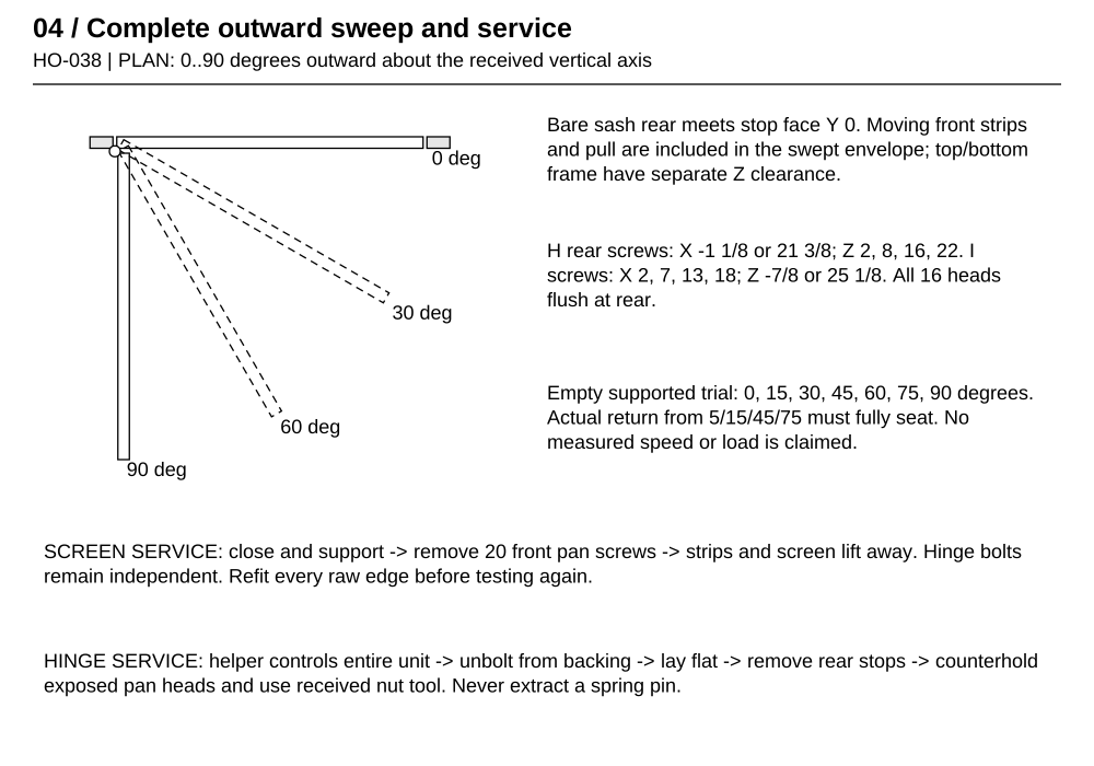
H / Full-height rear stop / quantity 2. 2 x 1/4 x 27 1/2 in (50.8 x 6.35 x 698.5 mm). Sound straight untreated wood, finished to the listed ACTUAL dimensions; no nominal-size substitution. X -1 5/8..3/8 and 19 7/8..21 7/8; Z -1 5/8..25 7/8; Y -1/4..0. Front stop face is Y 0, meeting bare rear wood, not a screw head or screen batten.
I / Between-stop horizontal bar / quantity 2. 19 1/2 x 1/4 x 2 in (495.3 x 6.35 x 50.8 mm). Sound straight untreated wood, finished to the listed ACTUAL dimensions; no nominal-size substitution. Between H, X 3/8..19 7/8; lower Z -1 5/8..3/8, upper 23 7/8..25 7/8. Rear stop clear aperture 19 1/2 x 23 1/2; nominal sash overlap 1/4 in on all four sides.
J / Specified practice backing strip / quantity 2. 1 1/2 x 1 1/2 x 27 1/2 in (38.1 x 38.1 x 698.5 mm). Sound straight untreated wood, finished to the listed ACTUAL dimensions; no nominal-size substitution. Existing separately secured practice blocking must provide this full section at X -1 5/8..-1/8 and 20 3/8..21 7/8, Y -1 3/4..-1/4. Its support to the building/test fixture is a separate site input; these strips do not stand by themselves.
K / Pull stand-off / quantity 2. 3/4 x 1/2 x 3/4 in (19.05 x 12.7 x 19.05 mm). Sound straight untreated wood, finished to the listed ACTUAL dimensions; no nominal-size substitution. On free stile X 19..19 3/4, Y 3/4..1 1/4, Z 10..10 3/4 and 13 1/4..14. Two posts leave 2 1/2 in clear vertically.
L / Vertical pull bar / quantity 1. 3/4 x 1/2 x 4 in (19.05 x 12.7 x 101.6 mm). Sound straight untreated wood, finished to the listed ACTUAL dimensions; no nominal-size substitution. X 19..19 3/4, Y 1 1/4..1 3/4, Z 10..14. Ease edges R<=1/8. Grip gap 1/2 in to stile front; never use mesh as a pull.
W1 / 8 / #8 x 2 1/2 in stainless flat-head wood screw. Fixed frame corners, four upward from lower A and four downward from upper A. Actual major OD<=.164 in and head OD<=5/16; seat flush.
W2 / 8 / #8 x 3 1/2 in stainless flat-head wood screw. Two at each sash corner, horizontally through 2 1/2 in C and 1 in into D. Same head/major limits as W1.
W3 / 20 / #6 x 3/4 in stainless pan-head wood screw. Screen clamps only; head OD<=1/4 and height<=1/8, major OD<=.138. Do not countersink thin F/G.
W4 / 16 / #6 x 3/4 in stainless flat-head wood screw. Rear stops only, crossing 1/4 in stop and entering 1/2 in frame. Head OD<=1/4; flush on rear for direct backing contact.
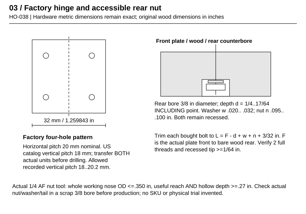
H1 / 2 / Sugatsune HG-SHL32 intact spring hinge. Official catalog H/W 32 mm (1.259843 in), four 3.2 mm bores, nominal 20 mm horizontal pitch and 18 mm vertical pitch in the retained US catalog. Transfer actual factory holes; receive the complete H/W<=1 5/16 in, barrel/coil/collar radial envelope<=7/32 in and e 0.18..0.22 in measured from the BARE WOOD front bearing plane to the pin AXIS. The catalog section gives 5 mm from the rear-leaf bearing plane to that axis (5/25.4=.196850 in), NOT the sheet thickness and not the outside coil face. Receive that actual axis datum and complete coil before machining; do not infer it from a photograph. The product lists closed depth 10 mm, which is not used as coil diameter or a standalone axis dimension. These last envelopes are ORIGINAL RECEIVING LIMITS, not unpublished catalog facts. Actual vertical pitch 18..20.2 mm and horizontal pitch 19.5..20.5 mm must fit the shown wood zones; choose matching units and record both patterns. No catalog load/cycle test transfers to this sash.
H2 / 8 / #4-40 x 1 1/4 in full-thread stainless pan-head machine screw stock. Trim EACH after measuring its own joint. Major OD 0.105..0.112, head OD<=.225 and height<=.085. Source screw must pass each actual 3.2 mm factory hole freely; never drill the hinge larger. Matched under-head length L=F-d+w+n+3/32 in, where F is actual plate front to bare wood rear, d is actual rear counterbore depth, w/n are actual washer/nut gauges. Trim to L within .005 in, deburr, then verify 2 complete threads beyond nut and tip>=1/64 in recessed from wood rear.
H3 / 8 / #4 flat washer. Actual OD<=1/4, bore freely passes H2, thickness w 0.020..0.032 in; one in each rear counterbore under nut.
H4 / 8 / #4-40 hex nut. NBK SHNS-#4-40 is a real dimensional candidate, published AF 1/4 and thickness .098 in. Receive actual thickness n 0.095..0.100, corner diameter<=.300; no strength rating inferred. One behind each H3; do not substitute a taller nut.
M1 / 6 / 1/4-20 x 3 1/4 in full-thread hex bolt. Through fixed frame, H stop and J practice backing at X -7/8 or 21 1/8, Z 3, 12, 21. Head OD across corners<=.520, height<=.180; no end in the sash sweep.
M2 / 12 / 1/4 flat washer. Actual OD<=3/4, thickness 1/16 +/-0.005; one under each M1 head and one behind backing under nut.
M3 / 6 / 1/4-20 nylon locknut. Actual height<=.230, corner OD<=.520. Verify 2 complete protruding threads beyond actual nylon. Keep at least 1 in rear service space. No wall/load rating supplied.
W5 / 2 / #6 x 1 1/2 in stainless pan-head wood screw. Pull only, head OD<=1/4, H<=1/8, major OD<=.138; from Y 1 3/4 toward 1/4 at X 19 3/8, Z 10 3/8 or 13 5/8. Cross 1/2 in bar and 1/2 in post, enter 1/2 in stile.
Rule, caliper, square, depth stop, clamps and supported saw; drill/driver and backing block.
3/16 in first-member wood-screw clearance; trial softwood pilots 7/64 for #8, 3/32 for #6; 5/32 in #4 machine clearance and 9/32 in quarter through bores.
3/8 in flat-bottom rear counterbore tool with measured point/stop; small metal saw, sacrificial 4-40 nut and file for bolt trimming. Receive an actual thin-wall 1/4 in AF nut tool: ENTIRE working nose OD<=.350 in, reach into the counterbore>=.27 in and hollow depth>=.27 in for nut plus protruding thread. Check its actual fit on the chosen nut/washer and a 3/8 in scrap bore BEFORE boring the frame; no generic wrench or invented SKU is assumed.
01. Choose a sheltered NON-egress utility opening and separately secured practice blocking. Reserve a clear outward sweep at least 21 1/2 in deep, with separate additional room for hands/helper outside the moving envelope, the whole 23 1/2 x 27 1/2 in fixed frame and 1 in behind the backing for nuts. A person must never rely on this opening for escape or put a head or body through a returning sash.
02. Receive both original HG-SHL32 hinges before cutting their zones. Read the retained factory drawing and its closing direction. With separate scrap leaves supported, confirm that surface mounting returns the coplanar faces toward closed; reject an opening-tension or different unit. Do not remove pins or unwind springs. Transfer the ACTUAL four holes of each unit rather than combining conflicting catalog pitch numbers.
03. Finish A-D to their actual sections, leaving 1/8 in kerf outside each finished blank. Mark X, Y, Z on the rear bare wood. Lay B between A to make 23 1/2 x 27 1/2 in outside and 20 1/2 x 24 1/2 clear. Compare diagonals; clamp the four corners flat before drilling.
04. Fix the fixed frame with W1 at X -7/8 and 21 1/8. Lower screws start Z -1 5/8 and run upward 2 1/2 in; upper screws start 25 7/8 and run downward 2 1/2. At each X use two distinct Y rows 3/16 and 9/16 in, not two screws on one axis. Each passes 1 1/2 in A and enters 1 in B. Drill 3/16 in clearance in A and a trial 7/64 in FULL 1 in cylindrical receiver plus measured drill point and 1/32 in reserve within the long stile.
05. Build the 20 x 24 in sash with D between C. Use W2 at Y 3/8, Z 7/8, 1 7/8, 22 3/8, 23 3/8 in. Left axes run from X 1/8 toward 3 5/8; right from 20 1/8 toward 16 5/8. First-member clearance runs through 2 1/2 in stile; receiving pilot is full 1 in plus measured point and 1/32 reserve. Clamp square, then seat all eight heads flush; none may project from a side or bare rear face.
06. With the sash hand-supported in its closed position, set all four perimeter edge gaps to 1/4 in nominal, accepted 3/16..5/16. Hinge axes are vertical on X 0 at Z 6 and 18 in centers, with their mounting planes on the common front wood Y 3/4. Receive both actual axis offsets e 0.18..0.22 in and keep their axes collinear without forcing pins. Receive the bare fixed hinge edge X<=-1/8 and sash hinge edge X>=+1/8; the hinge-side gap is 1/4..5/16, while the other perimeter gaps remain 3/16..5/16. Before boring, make four FRONT edge reliefs, two in fixed left B and two in hinged C: at each Z 6 or 18 center, Z center -3/4..Z center+3/4; remove from the actual gap edge to X -1/4 in fixed B or X+1/4 in C, only through front Y 1/2..3/4. Nominal removal width is 1/8 and depth 1/4 in. Receive relief outer abs X 1/4..17/64 in, floor Y 31/64..1/2, and height 1 1/2..1 17/32 centered at each actual hinge Z within .010 in; do not cut through the rear. Actual intact barrel/coil R<=7/32, axis X within .010, then has at least .02125 in side reserve. The mesh area stays well inboard of these zones.
07. Transfer the actual factory holes to wood. Nominal side hole axes are X+/-10/25.4 in, with Z 6 or 18 plus/minus 9/25.4 in; the allowed actual pitch is recorded before drilling. Drill 5/32 in through wood only. At every hole make a 3/8 in flat-bottom counterbore from the rear, depth 1/4..17/64 in including any tool point. Leave at least 1/32 in rear side ligament. Outside the local relief, front floor is at least 15/32 in; where the front relief overlaps the rear counterbore in X/Z, the remaining Y bridge is at least 7/32 in (nominal minimum .500-.265625=.234375). The 5/32 through-shaft bore stays outside the relief: minimum hole-center X 19.5/2/25.4 minus 5/64=.305733 in, greater than 1/4. These distinct webs must not be confused. Never counterbore the steel hinge. Before these production bores, receive a 1/4 in AF nut tool whose entire working nose OD<=.350 in, useful reach>=.27 in and internal hollow depth>=.27 in. Try the actual nut, washer, bolt tail and tool in a scrap 3/8 in counterbore at the full working depth. Reject a shoulder or shallow socket that cannot reach and turn; no such trial has been performed by the author.
08. Measure F, d, w, n for EACH of the eight H2 joints and calculate L=F-d+w+n+3/32 in. Put a sacrificial 4-40 nut on before trimming the bought 1 1/4 in screw, cut square to within .005 in, deburr and back the sacrificial nut off. Fit the pan head through the unmodified hinge; put H3/H4 in the rear recess. Verify two complete threads after the actual nut and at least 1/64 in tip recess. The calculated minimum recess is .01925 in at d .250, w .032, n .100 and positive .005 length error.
09. With a helper controlling the leaf, fasten both hinges through the exposed rear recesses. Hold each pan head while seating its nut; do not crush wood to conceal misalignment. Both leaves must bear flat. Confirm an empty supported outward swing through 0, 15, 30, 45, 60, 75 and 90 degrees. No mesh, stop or backing is fitted yet; do not release an unsupported leaf while attaching its second hinge.
10. Cut E to 17 x 21 in and lay it square on the sash FRONT, with 1 in overlap beyond the 15 x 19 in field. Lay F horizontally and G between them, covering every raw edge. Keep the outer 1 1/2 in hinged-stile band free so later mesh service does not trap a hinge bolt. Smooth the fabric without pulling the wooden frame out of square.
11. Install the twenty W3 pan screws at the rows in the cut list. Drill 9/64 in clearance in F/G and trial 3/32 in receiving pilots into sash wood: full cylinder 1/2 in, measured point<=1/16 and stop allowance<=1/64, total<=37/64. Received .740 in frame gauge leaves .161875 in below the deepest pilot. Do not countersink the thin strips, pierce a hand with a cut edge or let a point reach the bare rear.
12. Build the solid free-edge pull before fitting rear stops. Place the two K posts at X 19..19 3/4, Y 3/4..1 1/4, Z 10..10 3/4 and 13 1/4..14; fit L over them at Y 1 1/4..1 3/4, Z 10..14. The clear finger space is 1/2 in deep x 2 1/2 in high. Fix with two W5 from the bar front at X 19 3/8, Z 10 3/8 and 13 5/8, through 1 in combined bar/posts into 1/2 in sash stile. Drill 9/64 in clearance in bar/posts, then full 1/2 in receiver plus measured point/stop<=37/64. All points remain at least .161875 in inside .740 minimum stile. Grip this bar while opening/holding the leaf; never pull the fabric or put fingers in the hinge gap.
13. Fit H and I on the rear with their front faces at Y 0. The nominal stop aperture is 19 1/2 x 23 1/2, giving 1/4 in overlap onto the bare 20 x 24 sash rear. Hold the sash closed and ensure flat contact without wedging it; accepted overlap is at least 3/16. Stop screws are NOT driven into the sash.
14. Use sixteen W4 from Y -1/4 toward +1/2. On H use X -1 1/8 or 21 3/8 and Z 2, 8, 16, 22; on I use X 2, 7, 13, 18 at Z -7/8 or 25 1/8. These rows miss the frame corner and hinge bolts. Drill first-member clearance and full 1/2 in receiving pilots with measured point, keeping total penetration<=5/8 in of the .740 minimum frame. Seat rear heads flush.
15. Support the complete unit against the specified J backing with H stop strips acting as the 1/4 in rear stand-off. Match-drill six 9/32 in through joints at X -7/8 or 21 1/8 crossed with Z 3, 12, 21. Fit M1 with one M2 under head and one under M3. Nominal stack is .75+.25+1.5+.125+.230=2.855 in, leaving .395 in on a 3 1/4 in bolt; actual stack and two full threads govern. This defines the frame-to-backing joint only, not the upstream wall attachment.
16. Check all bare rear stop faces and panel edges. No rear hinge-nut tip or screw may touch backing or stop wood; all eight H2 joints remain inside their counterbores. Close gently and inspect the complete perimeter with light/feeler; repair tears, bowed parts or a gap that prevents the intended seating. This is an actual receiving check, not an insect or weather certification.
17. With the entire moving zone empty, hold and release only a small distance first. Check actual complete seating from 5, 15, 45 and 75 degrees without adding force or modifying a spring. Stop for a rapid impact, rubbing, twist, loose nut or failure to seat. The design has not been built; this builder acceptance step is not a claim that the author performed a closing trial. Do not add weight or an improvised spring to overcome a bind.
18. For screen service, close the sash and have a helper keep it supported. Remove W3, then lift G/F and E from the FRONT; the hinge zones are independent and their bolts stay in place. Clean or replace the identified screen as its maker directs. Refit every captured edge and pan screw, then repeat the whole supported swing and seating checks.
19. For hinge or stop service, keep the complete sash controlled, unbolt the entire frame from J with a helper and lay it flat. Remove H/I first to expose rear hinge nuts. Counterhold pan heads while undoing H4; support both hinge leaves throughout and never pull a spring pin. Refit hardware with each actual stack and all rear stops before remounting. Inspect splits, stripped pilots, loose nuts and screen damage each use; no durability, cleanability, insect-proof or load result is claimed.
Fixed frame and sash diagonals agree within 1/16 in without forcing; actual gaps 3/16..5/16 and rear overlap>=3/16 all around.
Both actual hinges have the received closing direction, complete envelope and collinear axes; their original holes remain unmodified. Both actual 5 mm-axis-datum hinges pass e .18..22 and whole coil R<=7/32; four front reliefs preserve local CB bridge>=7/32 and do not expose shaft holes.
All 8 trimmed hinge joints have two full threads and>=1/64 recessed tips; rear recesses remain accessible after removing stops.
No raw mesh edge, panhead, corner screw or rear mounting nut enters the whole outward sweep or handhold path. Screen service uses independent front strips.
The actual supported 0..90 degree swing is clear, and actual 5/15/45/75 degree return reaches every stop without a bind. A lifted/warped frame is rejected.
All 6 through-backing joints are seated on the specified full section with two actual full threads and rear access. No suitability of an unknown wall is inferred.
Inspect screen tears, corner square, stop contact, hinge fasteners and actual free movement before use. Follow the hinge and screen makers care directions; keep paint and grit out of the spring and pin.
Replace a damaged mesh strip or split timber component and repeat every actual fit check. Never lubricate or alter a spring contrary to the maker.
Unbolt and support the entire unit before accessing a hidden rear nut. This guide has no physical build, return-speed, insect, wind or service-life test.
Sugatsune HG-SHL32 official product and current HG-SHL catalog. Factory spring-closing type, four original holes and catalog dimensions only. Exact actual pattern is transferred. No manufacturer cycle/load claim transferred to this original sash.
Phifer Phiferglass and screen installation context. Identified insect-screen material and flat-frame, squarely aligned screen handling only. Original clamped wood geometry is independent; maker spline instructions are not misrepresented as approval of these clamps.
NBK SHNS-#4-40 hex nut dimensional candidate. Only 1/4 in AF and .098 in thickness dimensional candidate; actual receiving gauges control.