WA-001 Coarse-leaf cascade interceptor with separate open bypass

Separate broad loose leaves from a small attended nonpotable stream: water drops through an inclined slotted sheet into a lower lined channel while rejected leaves and a blinded-screen bypass leave over a higher apron.

Original small open-to-atmosphere apparatus for attended cold nonpotable service. No mains connection, elevated tank, treatment efficacy, output rate or pressure/load rating is specified. Unbuilt / untested. US customary dimensions control.

Before cutting

Materials and actual cuts

PartQuantityActual dimensionsMaterial / special cut
A Rebated outer cheek with integral curb230 in x 10 1/2 in x 3/4 in
762.0 x 266.7 x 19.05 mm
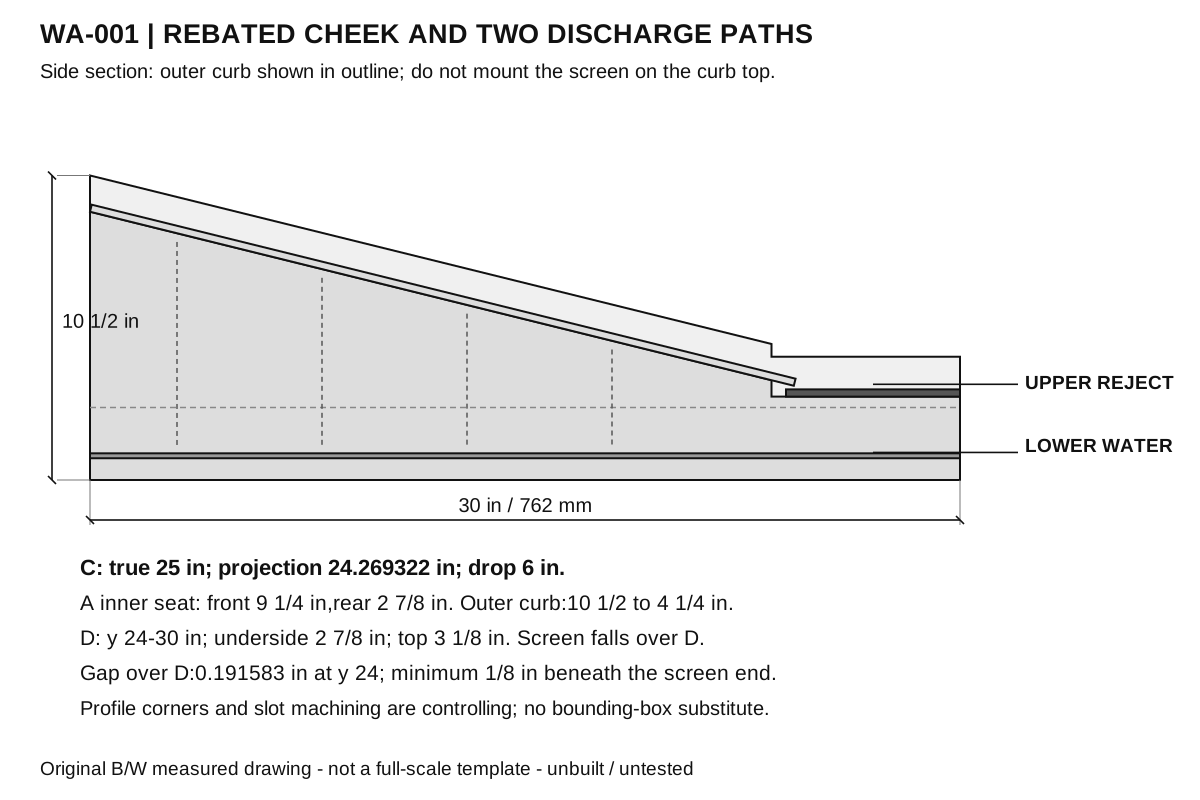
Flat exterior-bond birch plywood, actual listed thickness, no voids or sharp exposed edges; seal and cure exposed wood before liner fitting. Outer-quarter YZ profile: (0,0),(30,0),(30,4.25),(23.5,4.25),(23.5,4.690196),(0,10.5) in. Rebate the INNER1/2 in thickness to the lower seat profile (0,0),(30,0),(30,2.875),(23.5,2.875),(23.5,3.440196),(0,9.25). The outer 1/4 in thickness remains as the integral side curb.
B Underflow floor130 in x 14 in x 3/4 in
762.0 x 355.6 x 19.05 mm
Flat exterior-bond birch plywood, actual listed thickness, no voids or sharp exposed edges; seal and cure exposed wood before liner fitting. Square ends. Faces x=0-14, y=0-30, z=0-3/4 in in the fabrication pose.
C Machined coarse screen125 in x 14 7/8 in x 1/4 in
635.0 x 377.825 x 6.35 mm
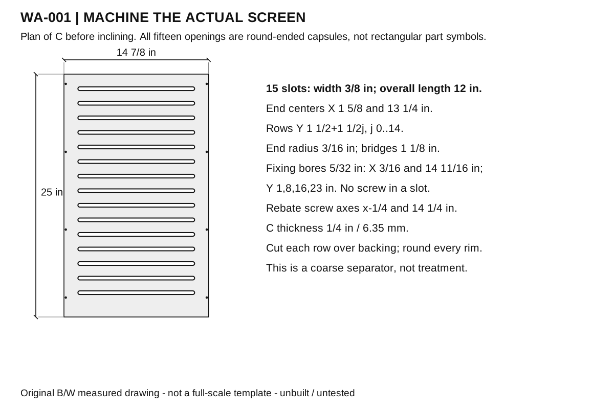
Virgin solid HDPE sheet, machine to the listed actual thickness; nonpotable cold service only. No welding or solvent joint assumed. Length 25 in follows the slope, not its horizontal projection. Fifteen crosswise capsule slots: local Y center 1.5+1.5 j in for j=0..14; slot X limits 1.4375-13.4375 in and width 3/8 in. End radii 3/16 in; centers X 1 5/8 and 13 1/4 in. Original slot sheet, not purchased unspecified mesh.
D Upper reject apron16 in x 14 7/8 in x 1/4 in
152.4 x 377.825 x 6.35 mm
Virgin solid HDPE sheet, machine to the listed actual thickness; nonpotable cold service only. No welding or solvent joint assumed. Fits between the integral curbs at x=-7/16-14 7/16 in,y=24-30 in, underside z=2 7/8 in. The sloping screen overlaps it without sharing a fastener.
E One unseamed underflow liner132 in x 20 in x 0.045 in
812.8 x 508.0 x 1.143 mm
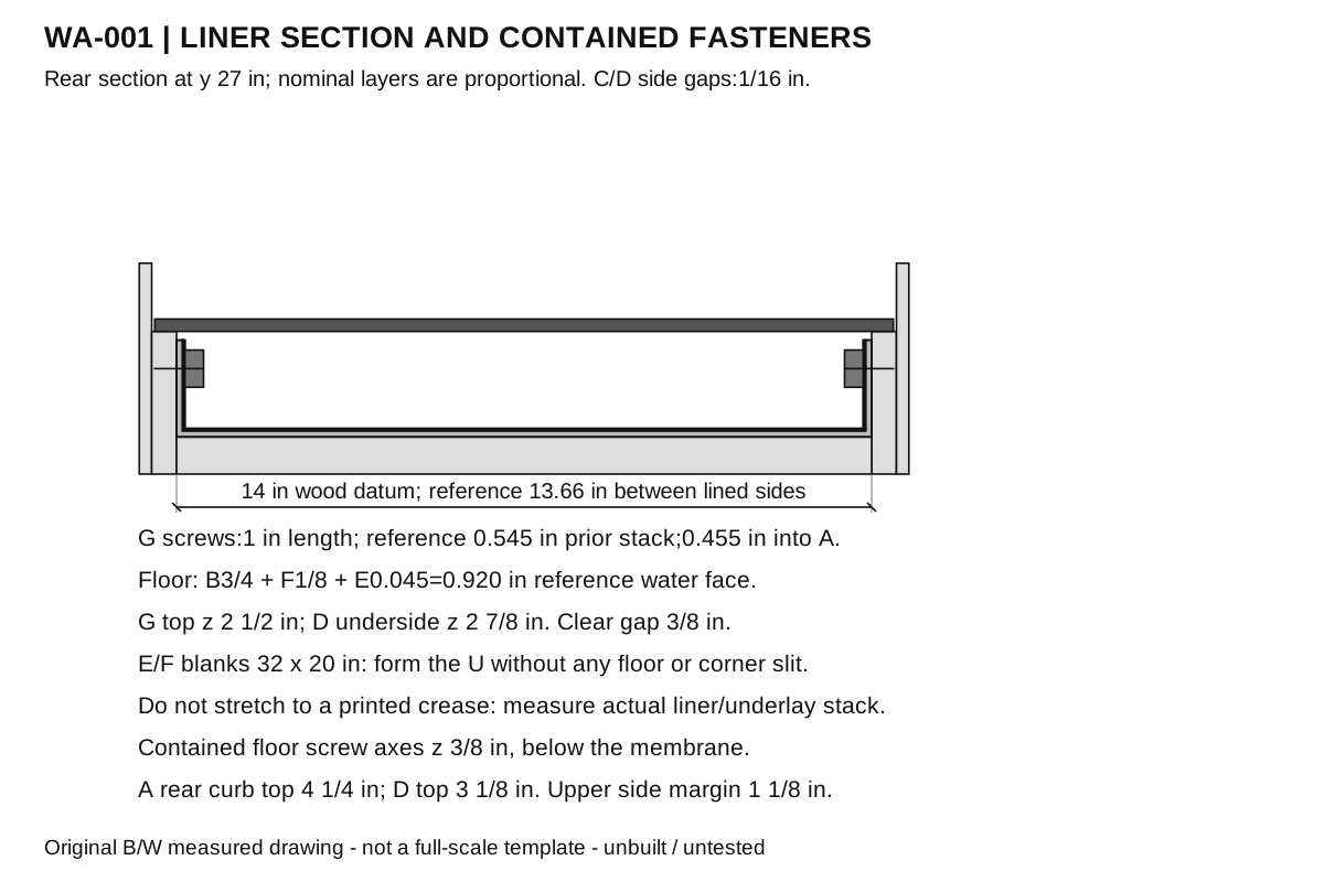
Elevate PondGard W56PL40801A raw EPDM liner stock, nominal 0.045 in / 1.143 mm; manufacturer +10/-20% thickness range 0.036-0.0495 in. Measure actual sheet; no generic roofing rubber substitution. One rectangle; length along Y. Do not cut floor or corner slits. Form a shallow open-ended U over the padded 14 in floor, then clamp only the upper side margins. Nominal material thickness is not a machined gauge.
F Soft liner-contact underlay132 in x 20 in x 1/8 in
812.8 x 508.0 x 3.175 mm
New clean nonwoven polyester liner underlay, measured compressed thickness 1/8 in, compatible with the selected EPDM; no oil, adhesive foam or abrasive scrap. One rectangle matching E. Keep it flat on the floor and up the two side faces; no folded lumps under the screen or liner clamps.
G Inside liner clamping strip230 in x 3/4 in x 3/8 in
762.0 x 19.05 x 9.525 mm
Clear straight-grained cedar, actual 3/8 in thick, rounded liner edges, exposed finish fully cured. Length along Y, height 3/4 in. Reference z=1 3/4-2 1/2 in; lower than the apron underside. Actual inward X offset equals the measured underlay plus membrane stack.
H Front fall-setting foot116 in x 3/4 in x 1/2 in
406.4 x 19.05 x 12.7 mm
Clear straight-grained cedar, actual 1/2 in thick; no loose stacked shims. Length along X, center under B at y=0-3/4 in. Attach beneath B; rear cheek edges rest on the same level ground.

Hardware and tools

Rule, square, marking gauge, calipers, depth-stop drill/driver, backed jigsaw or coping saw, countersink, files, sanding blocks, clamps and scissors reserved for liner. Special tools and drill diameters are stated in the steps.

Measured assembly reference

x left/right; y along the apparatus; z upward. Fabrication datum and any separate operating tilt are stated in steps.

Retained segments with the same part/instance belong to one machined stock piece, not additional parts. Positions and sizes below are US inches; rotations are degrees.

Part / instanceOrigin x,y,zSize / rotation
A / 1[-0.75, 0, 0][0.25, 30, 10.5] / [0, 0, 0]
A / 1[-0.5, 0, 0][0.5, 30, 9.25] / [0, 0, 0]
A / 2[14, 0, 0][0.5, 30, 9.25] / [0, 0, 0]
A / 2[14.5, 0, 0][0.25, 30, 10.5] / [0, 0, 0]
B / 1[0, 0, 0][14, 30, 0.75] / [0, 0, 0]
C / 1[-0.4375, 0, 9.25][14.875, 25, 0.25] / [-13.88654036262899, 0, 0]
D / 1[-0.4375, 24, 2.875][14.875, 6, 0.25] / [0, 0, 0]
E / 1[-2.5, -1, 0.875][20, 32, 0.045] / [0, 0, 0]
F / 1[-2.5, -1, 0.75][20, 32, 0.125] / [0, 0, 0]
G / 1[0.17, 0, 1.75][0.375, 30, 0.75] / [0, 0, 0]
G / 2[13.455, 0, 1.75][0.375, 30, 0.75] / [0, 0, 0]
H / 1[-1, 0, -0.5][16, 0.75, 0.5] / [0, 0, 0]

Numbered assembly

  1. Make the complete two-path interceptor first on a dry bench. It accepts a small attended hand-poured stream. It is not sized for a downspout and must never become the sole roof-drain route. x runs across the 14 in clear floor; y runs 30 in from input to discharge.
  2. Cut B 30 x 14 x 3/4 in and two separate A blanks 30 x 10 1/2 x 3/4 in. Mark the OUTER retained YZ profile from the cut list: its front height is 10 1/2 in and its rear height 4 1/4 in. Also mark the inner seat line z=9.25-(6/24.269322)y. At y 23 1/2 in the seat is z 3.440196 in; drop vertically there to z 2 7/8 in, then keep the rear seat flat to y 30 in.
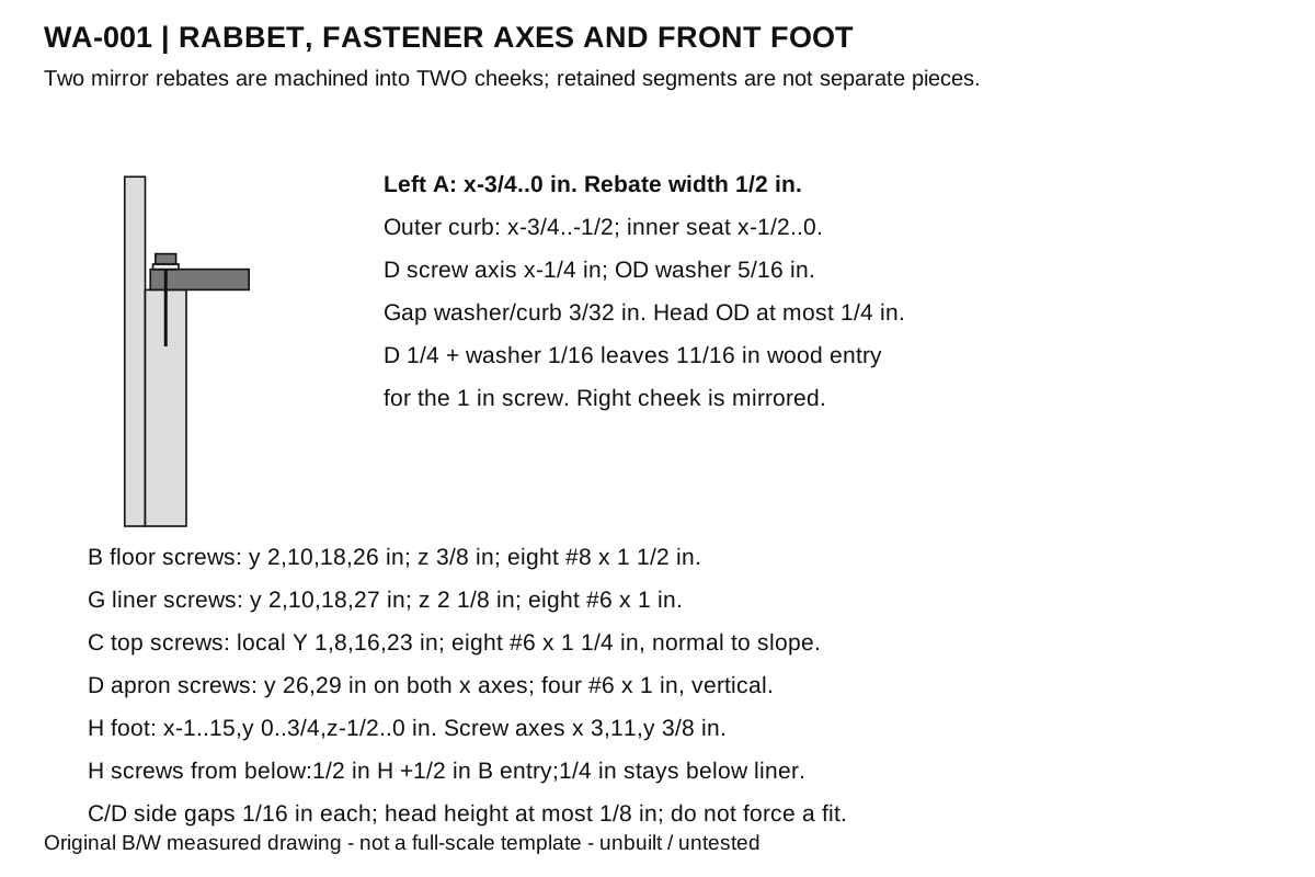
  3. Back and clamp each A and cut its outer profile. Lay its INNER face upward on a wide coplanar auxiliary surface. Using a clamped straightedge/template and a depth-stop router with a 1/4 in straight bit, remove the band between the outer top and the inner seat line to a depth of 1/2 in across the thickness. Take successive 1/8 in depth passes; keep the remaining outer 1/4 in intact. Square only the open rear step with a sharp chisel over backing. The two machined rebates must mirror inward and support C/D while their outer quarters remain higher as side curbs. Round liner-contact edges 1/8 in; do not round away the seat bearing.
  4. Stand A outside B at x=-3/4-0 and 14-14 3/4 in, keeping their lower edges flush with B underside z 0. From each outer A face drill four 5/32 in clearance holes at y 2,10,18,26 in and z 3/8 in. Pilot B edges 3/32 in to 3/4 in depth, then install eight #8 x 1 1/2 in flat-head screws. Countersink flush; their nominal tips finish 3/4 in inside B, below its top face.
  5. Cut H 16 x 3/4 x 1/2 in. Center it beneath B at x=-1-15 in, y 0-3/4 in. From H underside fit two #6 x 1 in screws at x 3 and 11 in, y 3/8 in, after clearance/pilots. The screws cross 1/2 in H and enter B 1/2 in, leaving 1/4 in below the liner face. Do not drive a tip through B.
  6. Cut C 25 x 14 7/8 x 1/4 in HDPE. Mark local X across its 14 7/8 in width and local Y along 25 in. For each j=0..14, mark a slot centerline at Y=1 1/2+1 1/2 j in. Drill 3/8 in end holes with centers X=1 5/8 and 13 1/4 in. Join their top/bottom tangents on the waste side to create fifteen 12 in overall long by 3/8 in wide round-ended slots. Keep full-thickness 1 1/8 in bridges between rows.
  7. File every slot wall and its radius smooth; remove burrs from BOTH screen faces. A cloth must pass through each slot without snagging. Do not replace the slots with notches open to an outer edge, and do not enlarge an individual slot to hide a drifting row. The uninterrupted outer X bands support the mounting screws.
  8. Set C underside in the two A rebates, with its front local Y 0 at global y 0,z 9 1/4 in and x=-7/16-14 7/16 in. Its back underside is at y 24.269322,z 3 1/4 in. The angle is 13.886540 degrees downward (use the dimensional seats, not an approximate angle setting). Mark four 5/32 in mounting holes per side at local Y 1,8,16,23 in and local X 3/16 or 14 11/16 in. The integral curbs flank the water path with 1/16 in side clearance per sheet edge; do not mount C on their tops.
  9. Remove C and drill its eight clearance holes over backing. Replace and pilot A 3/32 in normal to the sloping seat at the transferred axes, depth 1 in. Fit eight #6 x 1 1/4 in pan-head screws with 5/16 in OD x 1/16 in nylon washers. Use heads at most 1/4 in OD; the screw axes are 1/4 in from the curb face, leaving 3/32 in beside a 5/16 in washer. The 1/4 in sheet plus washer leaves 15/16 in nominal wood entry; stop before crushing the HDPE. The screen remains removable.
  10. Cut D 6 x 14 7/8 x 1/4 in. Lay it on the rear flat A rebates at y 24-30 in,z 2 7/8-3 1/8 in,x=-7/16-14 7/16 in, between the 4 1/4 in-high outer curbs. Its front lies under the final screen span: screen underside z 3.316583 in stays above apron top 3.125 in. This is a falling lap, not a pressure-tight seam. Drill 5/32 in holes at x=-1/4 and 14 1/4 in,y 26 and 29 in; fix with four #6 x 1 in pan heads and the same 1/16 in washers. Verify at least 1/32 in actual screen/apron gap before use.
  11. Remove C temporarily. Vacuum and wipe the floor and cheeks clean; let cured wood finish dry completely. Cut F and E 32 x 20 in each and let the EPDM lie flat without tension for 45 minutes before fitting. Lay F with 1 in overhang at each open end, then E above it, free of tension. Fold the two long margins upward against A, leaving the floor continuously covered. There is no end dam: both mouths stay open.
  12. Cut G two 30 x 3/4 x 3/8 in strips and round their rear contact edges. Clamp them against the liner sides at z 1 3/4-2 1/2 in. For the reference 1/8 in underlay plus 0.045 in membrane, their inner faces are x 0.545 and 13.455 in. Actual stack thickness can differ; keep both strips against the supplied stack rather than forcing the reference offset.
  13. From each G inward face drill four 9/64 in wood-screw clearance holes at y 2,10,18,27 in,z 2 1/8 in; pilot the A behind 3/32 in. Fit eight #6 x 1 in pan-head screws. With the reference 0.545 in strip/liner/underlay stack, wood entry is 0.455 in and the tips remain inside the 3/4 in cheek. Keep the liner floor completely unpunctured; trim only loose side tails above the clamp tops after confirming the U fold.
  14. Replace C. Check at y 24-30 in that the G top z 2 1/2 in remains 3/8 in below D underside z 2 7/8 in. G screws at y 27 in are offset 1 in from apron screws at 26 and 29 in; floor screws are at z 3/8 in, well below. There must be no pointed metal behind the membrane, rubbing slot edge or folded liner bunch blocking the lower rear mouth.
  15. Move the empty apparatus by both cheeks to a flat ground-level impervious trial area, never by C. H raises the input end 1/2 in; both rear cheek ends bear evenly. Keep the space beneath the rear apron visually open. Place the whole outlet over a separately contained low catch area, with the lower receiving mouth clear from approximately z 0.92 to 1.5 in and the separate upper reject mouth near z 3.125 in in the fabrication reference. Do not bridge a walkway, wall or occupied opening.
  16. Pour a quart of cold nonpotable water slowly onto the first two slot rows, keeping the lower channel depth below 1/2 in. Observe underflow exiting below D. Then add a few broad clean leaves and confirm they stay above the slots and can be brushed onto D while flow is stopped. Finally cover the slots with a temporary loose solid sheet and repeat a SMALL pour: all bypass must remain on top to the reject mouth. Remove the cover. Stop the input before any side spill; no rated storm flow or self-cleaning claim is made.
  17. After the attended check, stop all input, remove leaves by hand with the screen stationary and let both paths drain. Remove the eight C screws if the underside needs cleaning, then inspect the liner by lifting its loose open-end margin without dragging a tool on it. Dry the liner, both sheet faces and wood before storage. Never leave this open apparatus connected during unattended rain.

Checks

Use and maintenance

Cold nonpotable service water only. Never drink, cook, wash food, irrigate edible parts or supply animals from this apparatus.

An open coarse separator is not a microbial filter, disinfection device or mosquito barrier. Drain and dry after the attended session; do not leave an open stored-water habitat.

This design is not a storm-drain, structural or flood-control installation. Stop at backup, bypass outside the intended catch area, a loose joint or a damaged membrane.

Stop input before brushing the slots. Lift out broad debris; do not ram a rod through the slot and membrane below.

After each session drain both open ends, remove C when needed, and wipe the liner over soft backing. Follow the membrane maker cleaning guidance; isolate petroleum/oils and abrasive cleaners.

Inspect every capsule bridge for a crack, the eight screen holes for elongation, and G for loose edges. Replace a damaged screen or punctured membrane; do not hide damage with unverified sealant.

After drying, store under cover with no weight on C. Recheck the falling lap and contained screw tips whenever a liner, washer or wood piece is replaced.

Measured interface notes

All positions use a dry fabrication datum before H produces the small operating fall. The whole rigid frame tilts together; no moving joint or water container is suspended.

E/F scene entries are flat-stock references only. Their installed U section is shown in plate 3; they are flexible sheets, not flat blocks left across the open channel.

The nominal membrane thickness 0.045 in is preserved as a decimal; actual manufacturer range 0.036-0.0495 in and compressible underlay make clamp X coordinates reference values. Floor clear width remains more than 13 in at the reference stack.

A coarse slot sheet cannot intercept dust, dissolved chemicals or microorganisms and cannot seal a receiving reservoir against insects. This apparatus ends in an open free discharge and does not alter a building drain.
Retained cheek profile, true inclined screen, falling lap and distinct upper/lower paths Actual fifteen machined capsule slots, eight fixing bores and retained outer bands Installed U liner section, honest sheet thickness and clamp/floor screw tip envelopes Actual rebate and curb section, complete fastener axes, washer clearance and front foot position

Primary context

Rutgers Cooperative Extension: Rain Barrels Part II: Installation and Use, FS1118 Source

Elevate / Amrize: PondGard Rubber Liners, TIS101, August 20, 2025 Source

Elevate / Amrize: PondGard EPDM Design and Installation Guide, July 2025 Source