WA-002 Hand-indexed rotary open-channel water diverter

Direct a small attended nonpotable stream into one of two low removable receivers by pinning an open sloping chute at its selected yaw; drain and wipe before changing paths.

Original small open-to-atmosphere apparatus for attended cold nonpotable service. No mains connection, elevated tank, treatment efficacy, output rate or pressure/load rating is specified. Unbuilt / untested. US customary dimensions control.

Before cutting

Materials and actual cuts

PartQuantityActual dimensionsMaterial / special cut
A Fully ground-bearing base140 in x 36 in x 3/4 in
1016.0 x 914.4 x 19.05 mm
Exterior-bond birch plywood, actual listed thickness; void-free, sealed and fully cured. Datum(0, 0, 0) is front-left underside; O=(20, 6) in plan. Two carriage heads finish flush underneath.
B Rotating carrier with curved guide slot116 in x 12 in x 3/4 in
406.4 x 304.8 x 19.05 mm
Exterior-bond birch plywood, actual listed thickness; void-free, sealed and fully cured. Local x=-6..6, y=-2..14; installed z 1..1 3/4 in. Main pivot raw(6, 2): 27/64 in bore, finished diameter at most 0.423 in; index raw(10, 4): 13/32 in bore. Slot centerline R 8 in, angles+-30 deg from local+y, width 1/2 in, end-cap R 1/4 in. Endpoint centers raw(2, 8.928203), (10, 8.928203)in.
C Sloping open chute floor118 in x 4 1/2 in x 1/2 in
457.2 x 114.3 x 12.7 mm
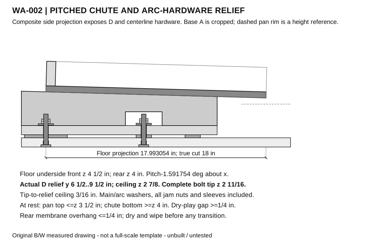
Exterior-bond birch plywood, actual listed thickness; void-free, sealed and fully cured. True 18 in length; underside front z 4 1/2 in, rear z 4 in. Pitch-1.591754 deg about x; sidewalls/dam/clamps share this pitch before yaw.
D Relieved sloping support beam216 in x 3 in x 3/4 in
406.4 x 76.2 x 19.05 mm
Clear straight-grained hard maple, actual 3/4 in thick; fully cured water-resistant finish. Raw blank 16 x 3 in; finished profile front height 2.805577 in, rear 2.360961 in. Full-width bottom notch local y 6 1/2..9 1/2 in, ceiling global z 2 7/8 in. Bottom z 1 3/4 in. Trace the actual profile; do not leave a rectangular beam across the arc hardware.
E Chute sidewall218 in x 2 1/2 in x 3/4 in
457.2 x 63.5 x 19.05 mm
Exterior-bond birch plywood, actual listed thickness; void-free, sealed and fully cured. Mounted beside C at local x-3..-2 1/4 and 2 1/4..3 in; bottom shares floor underside, so wall stands 2 in above bare floor.
F High front dam14 1/2 in x 2 in x 3/4 in
114.3 x 50.8 x 19.05 mm
Exterior-bond birch plywood, actual listed thickness; void-free, sealed and fully cured. ON C: local x+-2 1/4, y 0..3/4, z 1/2..2 1/2 in before pitch. No front-bottom gap.
G Unseamed chute liner blank124 in x 12 in x 0.045 in
609.6 x 304.8 x 1.143 mm
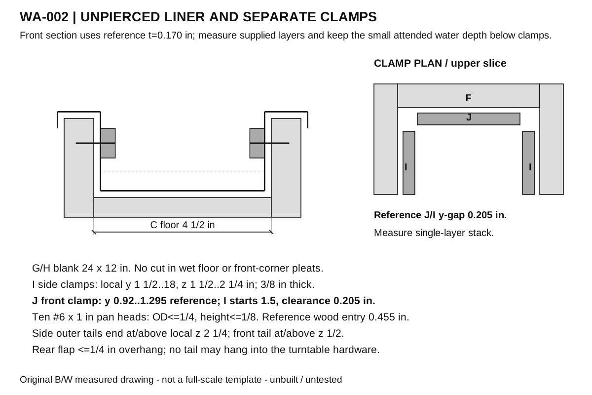
Elevate PondGard W56PL40801A raw EPDM liner stock, nominal 0.045 in / 1.143 mm; manufacturer +10/-20% thickness range 0.036-0.0495 in. Measure actual sheet; no generic roofing rubber substitution. Fit continuous U and uncut front-corner pleats. Rear free overhang at most 1/4 in. Mark and trim only free exterior surplus with sheet removed; never cut the wet floor/corners. Side outer free edges finish at/above local z 2 1/4 in; front edge at/above local z 1/2 in.
H Soft supported underlay blank124 in x 12 in x 1/8 in
609.6 x 304.8 x 3.175 mm
New clean EPDM-compatible nonwoven polyester underlay, actual reference 1/8 in. Relieve only this underlay at front corners to avoid thick ridges. Actual common side/floor stack is measured; 0.170 in is reference only.
I Inside side liner clamp216 1/2 in x 3/4 in x 3/8 in
419.1 x 19.05 x 9.525 mm
Clear cedar, actual 3/8 in thick; rounded edges and fully cured finish. Runs local y 1 1/2..18, z 1 1/2..2 1/4 in. Reference x=-2.08..-1.705 or 1.705..2.08 in; adjust to supplied single liner/underlay stack without forcing the channel.
J Inside front liner clamp13 1/4 in x 3/4 in x 3/8 in
82.55 x 19.05 x 9.525 mm
Clear cedar, actual 3/8 in thick; rounded and cured. Local x+-1 5/8, y 0.92..1.295, z 1 1/2..2 1/4 in reference. The side clamps start at 1.5 in, leaving 0.205 in longitudinal clearance.
K Receiver side locator82 in x 3/4 in x 3/4 in
50.8 x 19.05 x 19.05 mm
Clear hard maple, actual 3/4 in square section; rounded and cured. Two per side per pan, center local y 20/26 in. Inside face isW/2+1/8 in from the pan frame centerline; fit after measuring each bought pan. No front locator within the carrier sweep.
L Receiver rear locator26 in x 3/4 in x 3/4 in
152.4 x 19.05 x 19.05 mm
Clear hard maple, actual 3/4 in square section; rounded and cured. Local x+-3 in; front face y 16+actual pan L+1/8 in. Two underside screws at local x+-2 in, center across its 3/4 in width.
M Low-friction pivot spacing disc13 1/2 in x 3 1/2 in x 1/4 in
88.9 x 88.9 x 6.35 mm
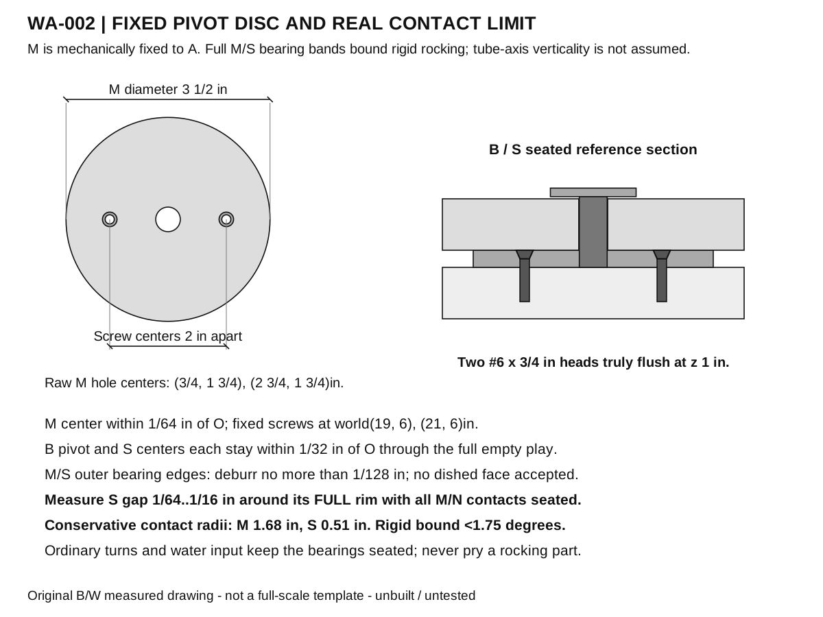
Solid virgin UHMW polyethylene sheet, actual 1/4 in. Round disc 3 1/2 in diameter; center bore 27/64 in. Two 5/32 in countersunk clearances at raw(3/4, 1 3/4), (2 3/4, 1 3/4)in. Fixed to A by two #6 x 3/4 in flat heads; M center within 1/64 in of O. Deburr outer top edge no more than 1/128 in; keep its bearing face flat.
N Low-friction glide disc31 1/4 in x 1 1/4 in x 1/4 in
31.75 x 31.75 x 6.35 mm
Solid virgin UHMW polyethylene sheet, actual 1/4 in. Round discs 1 1/4 in diameter; centers local(-4, 8), (4, 8), (0, 12). One centered #6 countersink each; do not use the rejected(+-4, 6) positions.
O Removable index pin11 15/16 in x 3/8 in x 3/8 in
49.2125 x 9.525 x 9.525 mm
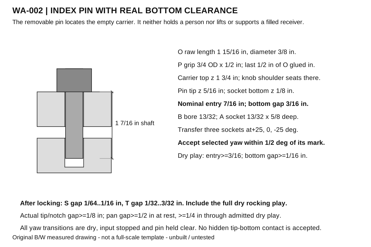
Straight hard maple dowel, actual 3/8 in diameter. Glue last 1/2 in into P; 1 7/16 in shaft, within 1/128 in, projects below knob. With knob on B top 1 3/4 in, pin ends at z 5/16 in. Nominal socket bottom z 1/8 in gives 3/16 in bottom clearance and 7/16 in base entry. Actual entry must stay>=3/16 in and bottom clearance>=1/16 in through admitted rocking play.
P Index pin grip13/4 in x 3/4 in x 1/2 in
19.05 x 19.05 x 12.7 mm
Straight-grained hard maple round stock, actual 3/4 in diameter. Centered 3/8 in through-bore; flat underside is the pin shoulder.
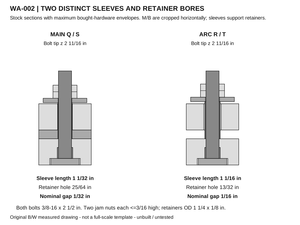
Q Main pivot smooth sleeve11 1/32 in x 13/32 in x 0.014 in
26.19375 x 10.31875 x 0.3556 mm
K&S Precision Metals 8136 raw brass tube, 13/32 in OD, .014 in wall, stated ID.378 in with+/-.002 in OD/ID tolerance. Dimensions are cut LENGTH x OD x WALL. Cut 1 1/32 in long, finished length within 1/128 in of target; end-face out-of-square at most 1/128 in across OD. Remove burrs without flaring. Assembled base-to-washer spacing sleeve, not a pressure tube.
R Arc guide smooth sleeve11 1/16 in x 7/16 in x 0.014 in
26.9875 x 11.1125 x 0.3556 mm
K&S Precision Metals 8137 raw brass tube, 7/16 in OD, .014 in wall, stated ID.409 in with+/-.002 in OD/ID tolerance. Dimensions are cut LENGTH x OD x WALL. Cut 1 1/16 in long, finished length within 1/128 in of target; end-face out-of-square at most 1/128 in across OD. Its outside runs in the curved slot; fit over the supplied 3/8 in bolt freely.
S Main retainer disc11 1/4 in x 1 1/4 in x 1/8 in
31.75 x 31.75 x 3.175 mm
Solid virgin UHMW polyethylene sheet, actual 1/8 in. Round 1 1/4 in diameter, center bore 25/64 in. A generic 13/32 in washer hole can pass over the thin main sleeve and is incompatible.
T Arc retainer disc11 1/4 in x 1 1/4 in x 1/8 in
31.75 x 31.75 x 3.175 mm
Solid virgin UHMW polyethylene sheet, actual 1/8 in. Round 1 1/4 in diameter, center bore 13/32 in. Bridges the 1/2 in curved slot and rests on R, leaving 1/16 in nominal carrier gap.
U Center parking drip pad14 1/2 in x 4 1/2 in x 1/8 in
114.3 x 114.3 x 3.175 mm
Clean nonwoven polyester absorbent shop mat, actual thickness at most 1/8 in; no oily rag. Loose on A at global x 17 3/4..22 1/4, y 23 1/2..28 in. Does not go under any pan/locator or enter the low carrier sweep. Parking drips only; not complete transit containment.
V Hand turning grip12 in x 3/4 in x 3/4 in
50.8 x 19.05 x 19.05 mm
Straight-grained hard maple dowel, actual 3/4 in diameter. Local x-5, y 11 in; glue 1/2 in into a blind B hole, leaving 1 1/2 in exposed. Do not use it to lift the whole apparatus.

Hardware and tools

Rule, square, calipers, 1/64 in feeler gauge, compass/protractor, depth-stop drill and backing, jigsaw, countersink, chisel, hacksaw and fine files, clamps, liner scissors, two hand wrenches. Bits: 3/8, 25/64, 13/32, 27/64, 1/2, 3/4, 7/8 in plus the pilot/clearance bits specified before cutting.

Measured assembly reference

x left/right; y along the apparatus; z upward. Fabrication datum and any separate operating tilt are stated in steps. Scene is a nominal park-pose reference. Actual retainer gaps,index bottom clearance,bolt-tip clearance andpan-mouth limits are measured after fitting.

Retained segments with the same part/instance belong to one machined stock piece, not additional parts. Positions and sizes below are US inches; rotations are degrees.

Part / instanceOrigin x,y,zSize / rotation
A / 1[0, 0, 0][40, 36, 0.75] / [0, 0, 0]
B / 1[14, 4, 1][12, 16, 0.75] / [0, 0, 0]
C / 1[17.75, 6.0, 4.5][4.5, 18, 0.5] / [-1.5917541765859022, 0, 0]
D / 1[18, 4, 1.75][0.75, 16, 2.8055770014376726] / [0, 0, 0]
D / 2[21.25, 4, 1.75][0.75, 16, 2.8055770014376726] / [0, 0, 0]
E / 1[17, 6.0, 4.5][0.75, 18, 2.5] / [-1.5917541765859022, 0, 0]
E / 2[22.25, 6.0, 4.5][0.75, 18, 2.5] / [-1.5917541765859022, 0, 0]
F / 1[17.75, 6.013888888888889, 4.999807061540182][4.5, 0.75, 2] / [-1.5917541765859022, 0, 0]
G / 1[14, 5, 5.17][12, 24, 0.045] / [0, 0, 0]
H / 1[14, 5, 5.045][12, 24, 0.125] / [0, 0, 0]
I / 1[17.92, 7.541087851287215, 5.957754517953881][0.375, 16.5, 0.75] / [-1.5917541765859022, 0, 0]
I / 2[21.705, 7.541087851287215, 5.957754517953881][0.375, 16.5, 0.75] / [-1.5917541765859022, 0, 0]
J / 1[18.375, 6.961311659900603, 5.973865629064992][3.25, 0.375, 0.75] / [-1.5917541765859022, 0, 0]
M / 1[18.25, 4.25, 0.75][3.5, 3.5, 0.25] / [0, 0, 0]
O / 1[23.8125, 7.8125, 0.3125][0.375, 0.375, 1.9375] / [0, 0, 0]
P / 1[23.625, 7.625, 1.75][0.75, 0.75, 0.5] / [0, 0, 0]
Q / 1[19.796875, 5.796875, 0.75][0.40625, 0.40625, 1.03125] / [0, 0, 0]
R / 1[19.78125, 13.78125, 0.75][0.4375, 0.4375, 1.0625] / [0, 0, 0]
S / 1[19.375, 5.375, 1.78125][1.25, 1.25, 0.125] / [0, 0, 0]
T / 1[19.375, 13.375, 1.8125][1.25, 1.25, 0.125] / [0, 0, 0]
U / 1[17.75, 23.5, 0.75][4.5, 4.5, 0.125] / [0, 0, 0]
V / 1[14.625, 16.625, 1.25][0.75, 0.75, 2] / [0, 0, 0]
N / 1[15.375, 13.375, 0.75][1.25, 1.25, 0.25] / [0, 0, 0]
N / 2[23.375, 13.375, 0.75][1.25, 1.25, 0.25] / [0, 0, 0]
N / 3[19.375, 17.375, 0.75][1.25, 1.25, 0.25] / [0, 0, 0]
K / 1[6.447439949672125, 20.64451792121396, 0.75][0.75, 2, 0.75] / [0, 0, 25]
K / 2[3.9117303792279277, 26.08236464343386, 0.75][0.75, 2, 0.75] / [0, 0, 25]
K / 3[16.81333526390381, 25.47821428987321, 0.75][0.75, 2, 0.75] / [0, 0, 25]
K / 4[14.27762569345961, 30.91606101209311, 0.75][0.75, 2, 0.75] / [0, 0, 25]
L / 1[5.077974331127352, 30.90178256546117, 0.75][6, 0.75, 0.75] / [0, 0, 25]
K / 5[22.506933895818705, 25.795177986178736, 0.75][0.75, 2, 0.75] / [0, 0, -25]
K / 6[25.042643466262902, 31.233024708398634, 0.75][0.75, 2, 0.75] / [0, 0, -25]
K / 7[32.872829210050384, 20.961481617519485, 0.75][0.75, 2, 0.75] / [0, 0, -25]
K / 8[35.40853878049458, 26.399328339739384, 0.75][0.75, 2, 0.75] / [0, 0, -25]
L / 2[29.484178946652747, 33.437492135905366, 0.75][6, 0.75, 0.75] / [0, 0, -25]

Numbered assembly

  1. Build one hand-positioned open water-routing apparatus with two fixed low receivers and three indexed yaw positions: left, +25 degrees; center dry parking, 0 degrees; right, -25 degrees. All movement is done after stopping input, draining to the selected pan and wiping the chute. It is not an automatic valve, a storm diverter or a closed plumbing connection.
  2. Obtain two Cambro 22CW pans before cutting locators. The manufacturer gives external 12 3/4 x 10 7/16 in and 2 1/2 in pan depth; the latter is not a separately toleranced installed height. Accept only actual outside L 12 5/8..12 7/8 in, W 10 3/8..10 1/2 in, total height including flange<=2 3/4 in. These are design acceptance bounds, not manufacturer tolerances. Dedicate both to NONPOTABLE service. They will sit directly on the 3/4 in base; do not modify them or infer the open mouth from outside dimensions.
  3. Cut A 40 x 36 x 3/4 in and B 16 x 12 x 3/4 in. On A mark O=(20, 6)in and the fixed arc spindle=(20, 14)in. On B use its raw front-left datum: main pivot(6, 2), index(10, 4), turning grip(1, 13)in. In the assembly, B local x=-6..6, y=-2..14 in, and bottom z 1 in. Check both rectangular diagonals before machining.
  4. Scribe all raw pivot/arc centers and compass arcs BEFORE drilling away the main compass center. Machine B main through-bore 27/64 in, index through-bore 13/32 in, and turning-grip blind bore 3/4 in diameter x 1/2 in deep from the TOP. For the curved guide, scribe R 7 3/4 and 8 1/4 in arcs about raw(6, 2)between angles-30 and+30 degrees relative to local+y. End centers are raw(2, 8.928203)and(10, 8.928203)in. Drill 1/2 in end bores through backing and join tangential boundaries with a fine saw; file the actual curved slot smooth, minimum 1/2 in wide throughout and no wider than 17/32 in. The rounded slot ends are physical travel stops, not a rectangular opening.
  5. At both A spindle centers drill 13/32 in through. On the UNDERSIDE counterbore 7/8 in diameter x 3/16 in deep; then chisel a 7/16 in square neck pocket from z 3/16 to 1/2 in. Select 3/8-16 x 2 1/2 in carriage bolts with head OD<=13/16 in, height <=3/16 in, and neck <=7/16 in across flats x 5/16 in long. Head underface seats at z 3/16 in, tip z 2 11/16 in, and no metal may protrude below A. Reject incompatible neck/head shapes instead of crushing the wood to seat them.
  6. Cut M and three N from actual 1/4 in UHMW, then S/T from actual 1/8 in sheet. M is 3 1/2 in diameter with 27/64 in hole. N are 1 1/4 in diameter. S/T are 1 1/4 in diameter; S bore 25/64 in, T bore 13/32 in. Drill over backing and deburr every lip. The smaller S hole must bear on Q end; an ordinary 13/32 in-hole washer can slide over the 13/32 in OD main sleeve and remove the intended running gap.
  7. Cut Q from the identified K&S 8136 tube to 1 1/32 in and R from 8137 to 1 1/16 in, each finished length within 1/128 in of its target and end-face out-of-square at most 1/128 in across OD. Deburr inside/outside without flaring or reducing the bearing ends. Fit the actual bolts freely through both sleeves; main bolt shaft/major-thread diameter must be 0.372-0.375 in. The maker lists ID.378+/-.002 for Q and.409+/-.002 for R. Do not force a burr, substitute nominal pipe or use a threaded surface as the carrier bearing.
  8. Cut D two 16 x 3 x 3/4 in maple blanks. From each beam front lower corner trace the eight actual retained-profile vertices in plate 2. Bottom is global z 1 3/4 in. At local y=-2 in finished height is 2.805577 in; at y 14 in it is 2.360961 in. Cut the sloped top and a FULL-WIDTH bottom relief from y 6 1/2 to 9 1/2 in, up to global z 2 7/8 in. This relief is essential for the fixed arc washer, nuts and bolt end during yaw; do not replace D with two solid rectangular blocks.
  9. Fasten D on B at local x=-2..-1 1/4 and 1 1/4..2 in, y=-2..14 in. From B UNDERSIDE drive four #8 x 2 1/4 in flat heads per beam at local x+-1 5/8, y=-1, 3, 10 1/2, 13 1/2 in. Heads are flush at z 1 in; tips z 3 1/4 in stay inside the solid beam away from its relief. Pilot into maple and keep the relieved interval completely open.
  10. Cut C 18 x 4 1/2 x 1/2 in, E two 18 x 2 1/2 x 3/4 in, and F 4 1/2 x 2 x 3/4 in. C true length 18 in falls 1/2 in, so its projected length is 17.993054 in and pitch-1.591754 degrees. Fit E beside C with their bottoms flush; attach with four #6 x 1 1/4 in flat heads per side, local y 1 1/2, 6, 10 1/2, 15 1/2 in, z 1/4 in, from outer x+-3 in inward. Each crosses 3/4 in E and enters 1/2 in C without piercing its top.
  11. Place F ON the bare floor at local x+-2 1/4, y 0..3/4, z 1/2..2 1/2 in. Add two #6 x 1 1/4 in flat heads per E into F, axes local y 3/8, z 1 1/8 and 2 in. Add two #6 x 1 1/2 in flat heads from C underside at local x+-1 1/4, y 3/8 in, normal upward; they cross 1/2 in floor and enter 1 in of the 2 in-high dam. The side and bottom fasteners have different axes and contained tips.
  12. Seat the complete chute on D: front underside z 4 1/2 in, rear underside z 4 in; local floor x+-2 1/4 in. Fasten down through C into D with four #8 x 1 1/2 in flat heads per beam, local x+-1 5/8, y 1, 5, 11 1/2, 13 in, driven NORMAL to the sloping floor. Each crosses 1/2 in C and enters 1 in D. These y stations differ from the upward B-D screws. Countersink flush before any liner touches C; inspect the relief and all tips with the assembly still off A.
  13. Ease every liner-contact edge 1/8 in, clean and finish the wood, then allow full labeled cure. Make O/P and glue exactly 1/2 in of the 1 15/16 in index dowel into its 1/2 in-thick grip, leaving 1 7/16 in projecting. Glue V 1/2 in into its blind B bore. Let both glue joints cure fully. Clamp N at local(-4, 8), (4, 8), (0, 12)on B underside; one #6 x 3/4 in countersunk screw per disc crosses 1/4 in UHMW and enters 1/2 in B. Do not move the first two glides to y 6 in: they would collide with the fixed R 8 arc sleeve.
  14. Place the two bolts upward in A, then Q at O and R at(20, 14). Center M on O within 1/64 in and clamp it to A. From M TOP drive two #6 x 3/4 in flat heads at world(19, 6), (21, 6)in, z 1 down to 1/4 in; each crosses 1/4 in UHMW and enters 1/2 in A. Countersink only until no metal stands above the flat bearing face. Deburr the M/S outer bearing edges no more than 1/128 in; reject a dished face.
  15. Lower B onto M/N with R inside the curved slot, and fit S over Q, T over R. Each disc rests on its sleeve, not on B. Fit two 3/8-16 jam nuts per bolt, each no thicker than 3/16 in and corner envelope<=11/16 in. Finger-seat the lower nut, hold it while jamming the upper against it without crushing a sleeve. Nominal running gaps are 1/32 in under S and 1/16 in under T; verify each ACTUAL gap with a feeler after locking nuts: at least 1/64 in. Nominal sleeve lengths alone do not prove a gap through a distorted disc.
  16. The carrier main bore must not exceed 0.423 in; do not enlarge it while filing the arc slot. The fixed full M disc and the complete S retainer bound rigid dry rocking to less than 1.75 degrees under the required measured gaps/center limits; this does not assume a perfectly vertical tube. Plate 7 gives the contact geometry. Never pry or force the bore. Check each full retainer rim, including four quarter-points: actual S running gap must be 1/64..1/16 in, T gap 1/32..3/32 in at every point; main assembled lateral play at most 1/16 in total, centered about O. Retain the B pivot crosshair beyond its bore; project it onto the A datum with a square while gently taking up the full empty play: its center must stay within 1/32 in of O. Before lowering B and again after locking, use the marked A axes and component outside edges to locate their centerlines: every Q/S/main-nut/main-bolt AXIS point must project within 1/32 in of O; every R/T/arc-nut/arc-bolt AXIS point must project within 1/64 in of(20, 14), at every exposed height. These are axis offsets, not limits on the component outside diameters. Use a square to check both spindle assemblies. Use the marked O-to-(20, 14) line as+y for both pan frames; do not redefine it from a leaned hardware stack. No leaned sleeve or off-center retainer outside the stated axis offsets is accepted. Dress the exposed tips; do not add an unbounded cap above the measured envelope.
  17. With the chute EMPTY, swing slowly through its actual stops. Both must lie inside+-31 degrees; working marks are+-25 degrees and 0. The nominal arc tip z 2 11/16 in clears the D relief ceiling z 2 7/8 in by 3/16 in; dress each supplied tip to no higher than z 2 45/64 in and measure at least 1/8 in actual clearance through the full dry rocking/yaw envelope. Retainer OD 1 1/4 in and the sleeve must clear both relief side ends throughout travel. Hold the index pin in the other hand; never put fingers under the carrier. Stop at rubbing, a tight slot, unexpected lifting during an ordinary flat turn or an unknown hardware envelope. Only the separate EMPTY dry-play check gently takes up free retainer rocking; never pry or force the bore. Every ordinary turn and every water-receiving pose keeps all glides seated.
  18. Set each measured pan in its fixed frame yaw+25 or-25 degrees around O, external front at local y 16 in and centered across that frame. At its matching working yaw, hold a 5 x 1 in horizontal card across the entire landing strip at local y 17.993054 in; it must enter the ACTUAL unobstructed mouth freely below the chute outlet. Confirm at least 1/2 in vertical clearance at rest, and at least 1/4 in through the full dry yaw/retainer-rocking envelope, from the actual pan flange to every rigid overhanging part. This is an actual interface check, not a claimed manufacturer interior dimension.
  19. Fit K/L after that pan check. Each side has two 2 in locators centered local y 20 and 26 in, inside faces atx=+-(actual W/2+1/8 in). Rear L front face isy 16+actual L+1/8 in; center its 6 in length across the frame. There is NO front locator. Mark two underside A screw axes per side block, y center+-1/2 in, centered in its 3/4 in width; rear block axes local x+-2 in, centered in its 3/4 in width. Use 20 #6 x 1 1/4 in flat heads upward through 3/4 in A into 1/2 in of each block, leaving 1/4 in before its top. Remove pans and the rotating assembly before underside fastening. Clamp locators to the EMPTY base on padded bench support, drive the underside screws, then return A to fully supported level ground before reinstalling the rotating assembly and pans. No fastener enters a factory pan.
  20. At each yaw+25, 0, -25 degrees use B index bore to TRANSFER a base socket; remove the rotating assembly and drill 13/32 in x 5/8 in deep from A top with a stop, leaving 1/8 in base below; never exceed 5/8 in depth. Nominal socket centers are listed in plate 1, but actual transfer controls alignment. Reassemble and ensure the pin shoulder seats on B while its tip has nominal 7/16 in entry in A plus 3/16 in bottom clearance. Mark a band 3/16 in above the pin tip: it must remain below A top even during dry rocking; verify actual bottom clearance>=1/16 in from the measured projection/shoulder height and probed socket depth. Verify selected yaw stays within 1/2 degree of its mark across the admitted pin/bearing play. A pin that bottoms on an untransferred hole or needs hammering is rejected. Center parking is dry, not a third water path.
  21. Fit H then G with 45 minutes liner relaxation, keeping one continuous wet floor and uncut front-corner pleats outside the high dam. Side liners climb the 2 in walls and fold over their tops; mark external surplus for trimming with the sheet removed. Rear free overhang is at most 1/4 in; side outer edge stays at/above local z 2 1/4 in, front edge at/above local z 1/2 in. Relieve underlay corner excess independently. No liner tail may hang toward the fixed arc hardware or the low turntable.
  22. Cut I two 16 1/2 x 3/4 x 3/8 in and J 3 1/4 x 3/4 x 3/8 in. Side clamps span local y 1 1/2..18, z 1 1/2..2 1/4 in; J spans x+-1 5/8 in at the front wall. Using the actual single layer stack, place J clear of both I starts: reference y 0.92..1.295 leaves 0.205 in. Use eight #6 x 1 in pan heads at side y 2 1/4, 7 1/2, 12 3/4, 17 1/4, z 1 7/8 in, directed outward into E; use two at front x+-1, z 1 7/8 in, directed toward F. Measure the compressed clamp-plus-liner-plus-underlay distance from each screw head underside to the receiving wood face: accept 1/2..5/8 in only. With the allowed screw-length range, this leaves at least 0.359375 in wood entry and at least 0.234375 in before a 3/4 in wall outer face. Reference stack 0.545 in gives 0.455 in nominal entry. Reject thick pleats under a clamp instead of using longer screws. Keep all heads above the actual 1/2 in-deep trial water and all corners smooth.
  23. Lay U only at global x 17 3/4..22 1/4, y 23 1/2..28 in, without going under pans or locators. Repeat the complete dry swing and three pin fits after lining. Stop input while changing paths: drain into the selected receiver, wick remaining water from the floor, withdraw the pin, turn by V and repin. The pad catches a few center-parking drips; it does not contain a flowing transit discharge. Operate over a separately contained ground-level place for the full small trial volume.
  24. For each working path separately, pin it first and place its empty receiver against the locators. Before input, all M/N bearing surfaces must be seated; do not hold the turning grip or rock the carrier while water is flowing. Hand-pour no more than 1 US quart total for the attended check, keeping actual water depth below 1/2 in and the receiver at least 1/2 in below its rim. Watch that every drop lands inside the actual mouth without touching a flange or loose liner fold. Stop before emptying or moving a pan. Drain, wipe, unpin and repeat the other path only when dry. No throughput, load or automatic shutoff rating follows from this procedure.
  25. After the session remove the pans for separate nonpotable cleaning, blot the pad and dry all liner folds. Lift the rotating assembly only after emptying and removing its retainers; do not lift by V alone. Inspect sleeve ends, disc holes, slot edges, blind index sockets, beam reliefs and countersinks before reassembly. Replace a split pin, oval bore, crushed sleeve or rough membrane-contact surface instead of tightening it out of sight.

Checks

Use and maintenance

Cold nonpotable service water only. Never drink, cook, wash food, irrigate edible parts or supply animals from this apparatus.

The open routing chute provides no filtration, disinfection or mosquito barrier. Drain and dry after the attended session; do not leave an open stored-water habitat.

This design is not a storm-drain, structural or flood-control installation. Stop at backup, bypass outside the intended catch area, a loose joint or a damaged membrane.

After every session remove the pans, clean only for their dedicated nonpotable use, and dry the loose parking pad. Never leave trapped standing water under the membrane folds.

Before yawing again inspect both brass sleeve ends for flaring or crushing, retainer discs for a dished face, and the curved slot for rough or ovalled edges. Replace a damaged sleeve/disc; do not erase a running gap by tightening harder.

Recheck both fixed M screws for truly flush heads, the M/S flat bearing bands, both actual stops, three transferred sockets and the four D-notch corners after any hardware change. A longer dressed bolt, a wider washer or relocated glide requires a new full sweep check before use.

Inspect each underside countersink and every membrane contact surface while empty. Replace split beam stock, loose glued grips, a bent index pin or cut liner before refitting; do not lift a filled pan by the turning grip.

Store dry under cover with no weight on the chute. Repeat the actual pan-mouth and height gauge whenever a receiver is replaced; catalog pan depth alone is not total installed height.

Measured interface notes

Scene is the nominal center-parking yaw. Global x/y/z positions are actual inches; C/E/F/I/J share x-pitch before the whole rotating group yaws about O=(20, 6). D is an actually machined profile, not its bounding box left solid.

The two raw tube parts are listed LENGTH x OD x WALL; their ID is identified manufacturer data. S has a 25/64 in hole deliberately smaller than Q outside diameter; a generic 13/32 in-hole washer can bypass Q.

Every low moving component and fastener ends inside the receiver-front radial gap; the high chute above z 4 in can pass over pans bounded below z 3 1/2 in. Complete washer/nut/bolt geometry must fit the beam relief throughout the bounded yaw.

This apparatus does not connect to a building drain, contain pressure, store water unattended, provide filtration or establish a flow/load rating. The<=1 quart instruction is an attended commissioning limit, not a physical trial already performed.
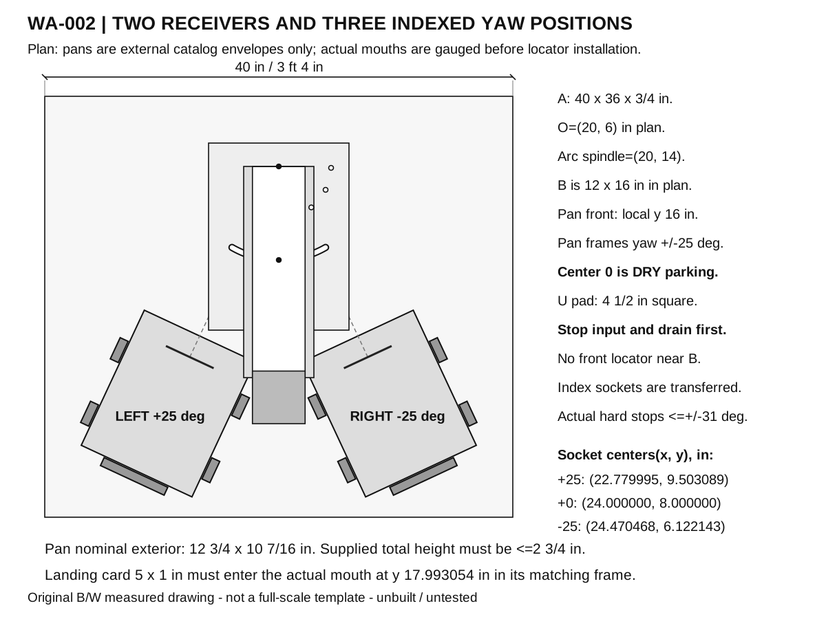
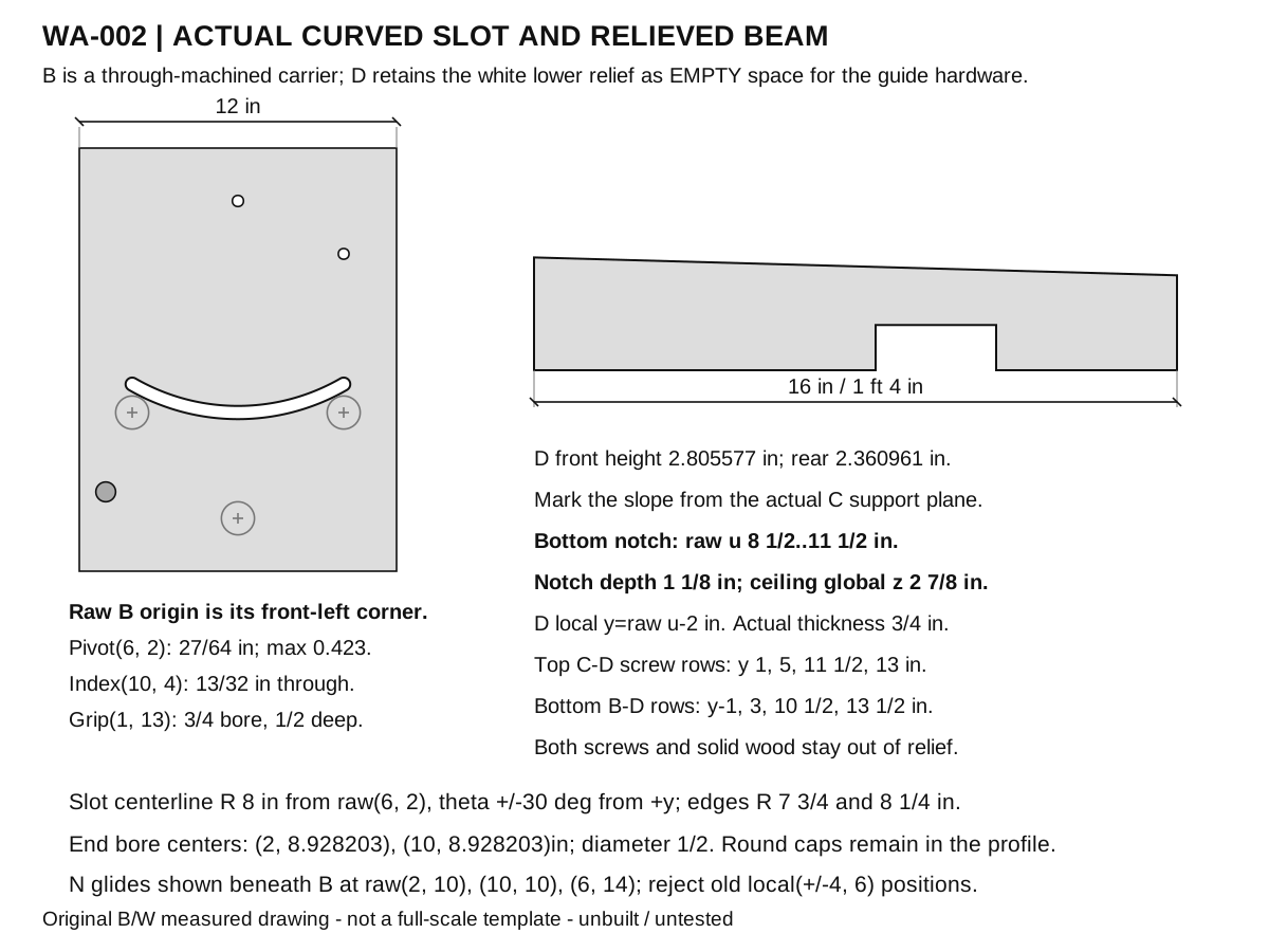
Measured fixed receiver frames,carrier,three index poses and center-only parking pad Actual annular through-slot,bores,glide positions and two full-width notched beam profiles Actual pitched floor/sidewall/dam,notched supports and complete spindle clearance elevations Separate real sleeve diameters,retainer bores,head/neck recesses,jam nuts and axial running gaps Actual sidewall/floor/clamp cross-section,unpierced membrane route and distinct front/side clamp extents Actual index pin,5/8in blind socket,nominal7/16in engagement and3/16in bottom gap with full-play acceptance Full measured fixed pivot disc with two flush screw axes and main support/retainer contact-band reference

Primary context

Rutgers Cooperative Extension: Rain Barrels Part II: Installation and Use, FS1118 Source

Elevate / Amrize: PondGard Rubber Liners, TIS101, August 20, 2025 Source

Elevate / Amrize: PondGard EPDM Design and Installation Guide, July 2025 Source

Cambro: Camwear Pans product specification, model22CW Source

K&S Precision Metals: 8137 Round Brass Tube,7/16in OD x.014in wall Source

K&S Precision Metals: 8136 Round Brass Tube,13/32in OD x.014in wall Source