Display two checked low/high water references above an opaque, shallow nonpotable service pan using a buoyant mechanical follower.
Original attended, open-pan level indicator. No fill valve, pressure vessel, potable treatment, certified depth accuracy or automatic overflow protection is built. Actual receiver fit, complete wet mass, low guide drag and water-reference comparisons are required. The apparatus is unbuilt and untested. Unbuilt / untested. US customary dimensions control.
| Part | Quantity | Actual dimensions | Material / special cut |
|---|---|---|---|
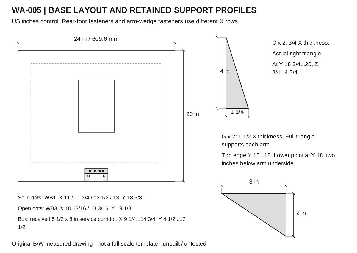
| A Fully supported base board | 1 | 24 in x 20 in x 3/4 in 609.6 x 508.0 x 19.05 mm | Sound flat exterior-bond plywood or straight-grain hardwood, finished to the listed actual size. No voids, splits or loose fibers. The base remains fully supported; no elevated tank or bench load rating is claimed. Global X 0..24, Y 0..20, Z 0...75. Keep the entire underside supported on a level bench or floor. WB1 axes: X 11, 11.75, 12.5, 13 at Y 18.375. WB3 axes: X 10.8125/13.1875, Y 19.125. Countersink underside heads fully flush. |
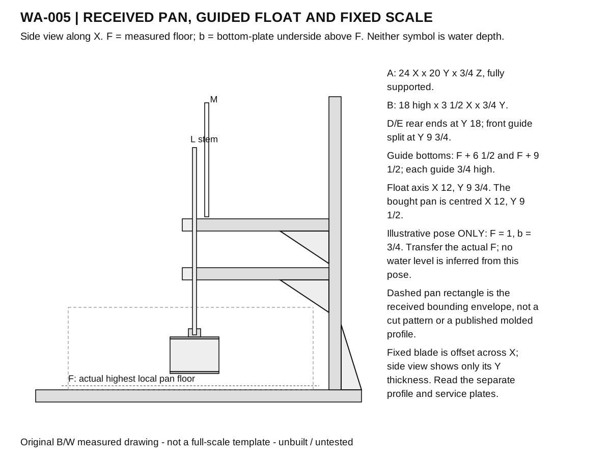
| B Rear mast | 1 | 18 in x 3 1/2 in x 3/4 in 457.2 x 88.9 x 19.05 mm | Sound flat exterior-bond plywood or straight-grain hardwood, finished to the listed actual size. No voids, splits or loose fibers. The base remains fully supported; no elevated tank or bench load rating is claimed. Install X 10.25..13.75, Y 18..18.75, Z .75..18.75, with grain along its 18 in height. Transfer every F-dependent arm/wedge row from the actual received pan floor. Do not assume the illustrative F = 1 in is the pan interior. |
| C Rear mast-foot gusset | 2 | 4 in x 1 1/4 in x 3/4 in 101.6 x 31.75 x 19.05 mm | Sound flat exterior-bond plywood or straight-grain hardwood, finished to the listed actual size. No voids, splits or loose fibers. The base remains fully supported; no elevated tank or bench load rating is claimed. Retain one right triangle in YZ: (18.75,.75), (20,.75), (18.75,4.75). X intervals 10.25..11 and 13..13.75. The finished part is triangular, not the full rectangular blank. |
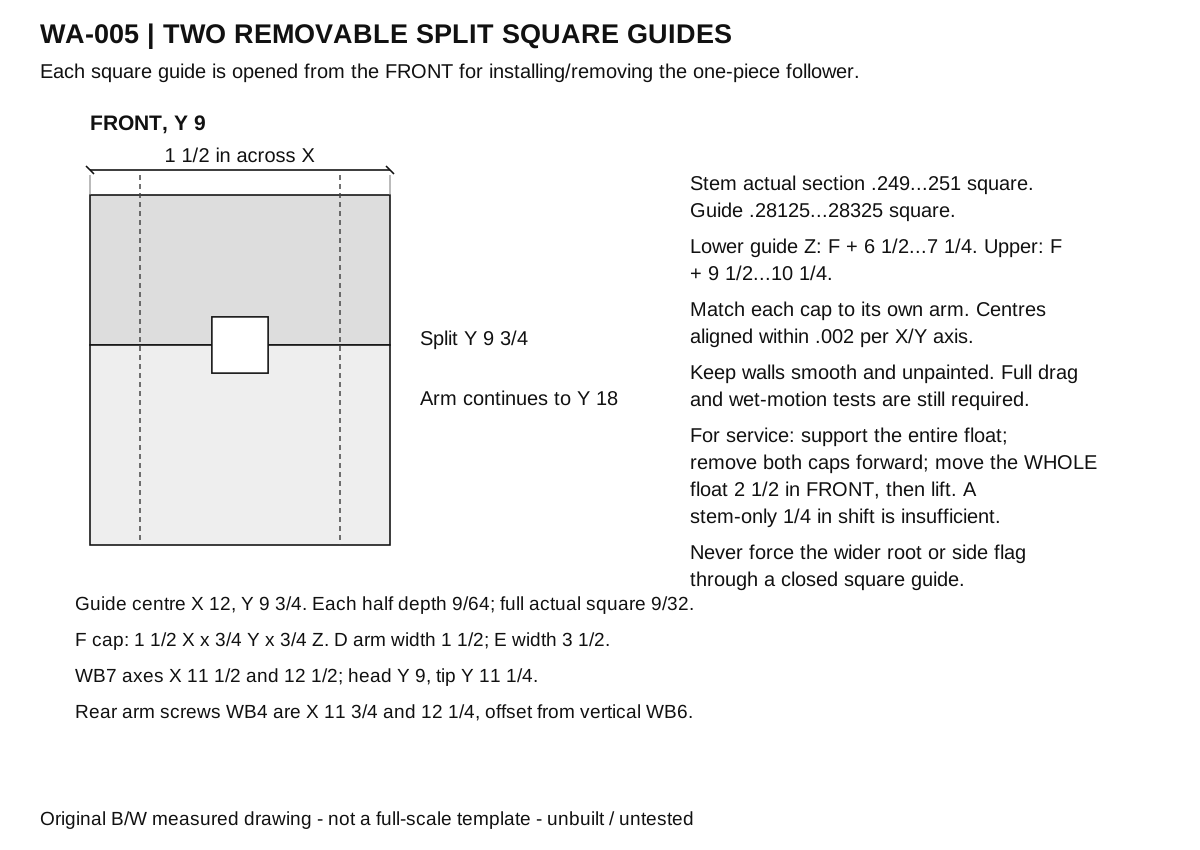
| D Lower split-guide arm | 1 | 8 1/4 in x 1 1/2 in x 3/4 in 209.55 x 38.1 x 19.05 mm | Sound flat exterior-bond plywood or straight-grain hardwood, finished to the listed actual size. No voids, splits or loose fibers. The base remains fully supported; no elevated tank or bench load rating is claimed. Install X 11.25..12.75, Y 9.75..18, Z F+6.5..F+7.25. At the front face remove the guide half-notch: X 12 +/- .140625, Y 9.75..9.890625, through Z. WB4 rear axes X 11.75/12.25, Z F+6.875. |
| E Upper guide and scale arm | 1 | 8 1/4 in x 3 1/2 in x 3/4 in 209.55 x 88.9 x 19.05 mm | Sound flat exterior-bond plywood or straight-grain hardwood, finished to the listed actual size. No voids, splits or loose fibers. The base remains fully supported; no elevated tank or bench load rating is claimed. Install X 11.25..14.75, Y 9.75..18, Z F+9.5..F+10.25. Same guide half-notch as D. WB4 axes X 11.75/12.25, Z F+9.875. Fixed scale clamp SF1 axes: X 14, Y 10.25/10.75. |
| F Removable front guide cap | 2 | 1 1/2 in x 3/4 in x 3/4 in 38.1 x 19.05 x 19.05 mm | Sound flat exterior-bond plywood or straight-grain hardwood, finished to the listed actual size. No voids, splits or loose fibers. The base remains fully supported; no elevated tank or bench load rating is claimed. Two matched caps, X 11.25..12.75, Y 9..9.75, at Z F+6.5 and F+9.5. The rear half-notch is X 12 +/- .140625, Y 9.609375..9.75, through Z. Together with the arm it forms a true 9/32 in square guide. WB7 axes X 11.5/12.5 at guide bottom + .375, directed along +Y. |
| G Arm underside support wedge | 2 | 3 in x 2 in x 1 1/2 in 76.2 x 50.8 x 38.1 mm | Sound flat exterior-bond plywood or straight-grain hardwood, finished to the listed actual size. No voids, splits or loose fibers. The base remains fully supported; no elevated tank or bench load rating is claimed. Lower YZ triangle: (15,F+6.5), (18,F+6.5), (18,F+4.5); upper triangle 3 in higher. Both occupy X 11.25..12.75. Vertical WB6 axes X 11.5/12.5, Y 17.25. Horizontal WB5 axes X 11.75/12.25, Z F+5.875 or F+8.875. Different X rows prevent hidden screw crossings. |
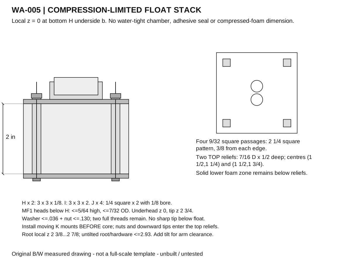
| H Float capture plate | 2 | 3 in x 3 in x 1/8 in 76.2 x 76.2 x 3.175 mm | Solid unfilled HDPE, such as King StarBoard standard material machined from oversize stock to the actual gauge. No foamed core, adhesive joint or transferred food-contact certification. Both 3 in square, actual thickness .124..126 in, centered X 12, Y 9.75 in the reference pose. Four received .125..126 in bores at local X/Y .375 or 2.625. Do not countersink: rounded MF1 heads seat below the lower plate. Upper H also has two mount bores at local X 1.5, Y 1.25/1.75. |
| I Closed-cell buoyancy core | 1 | 3 in x 3 in x 2 in 76.2 x 76.2 x 50.8 mm | One monolithic closed-cell crosslinked PE foam block, Plastazote LD45 candidate. Published data are typical only; actual finished dimensions and complete wet moving mass govern. Receive one monolithic closed-cell block, plan 2.995..3.005 in square and thickness 1.995..2.005. Four 9/32 in square through-passages on the H corner pattern. TOP ONLY: two 7/16 in diameter reliefs .500 +/- .001 in deep, at local (1.5,1.25)/(1.5,1.75). The lower foam section remains intact. Actual core height must not exceed the shortest J spacer; trim before assembly. No laminated or open-cell substitution. |
| J Compression-limiting square spacer | 4 | 2 in x 1/4 in x 1/4 in 50.8 x 6.35 x 6.35 mm | Solid unfilled HDPE, such as King StarBoard standard material machined from oversize stock to the actual gauge. No foamed core, adhesive joint or transferred food-contact certification. Finish four equal 2.000 +/- .001 in lengths, each .25 in square. Make a straight .125..126 in axial bore. They fit the larger foam passages and span the two H inside faces, so screw tightening stops on solid spacer ends rather than compressing the foam. |
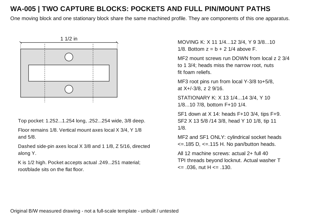
| K Slotted root/scale capture block | 2 | 1 1/2 in x 3/4 in x 1/2 in 38.1 x 19.05 x 12.7 mm | Solid unfilled HDPE, such as King StarBoard standard material machined from oversize stock to the actual gauge. No foamed core, adhesive joint or transferred food-contact certification. Two blocks, each 1.5 X by .75 Y by .5 Z. Centered top pocket: target 1.253 X by .253 Y, depth .375; received length 1.252..1.254, width .252...254, depth .374...376. Nominal pocket X .1235..1.3765, Y .2485...5015; leave the .125 nominal floor. Square the corners. Side-pin bores .125...126 along Y at local X .375/1.125, Z .3125. Vertical mount bores .125...126 at local X .75, Y .125/.625. Mounts and side pins use separate axes. |
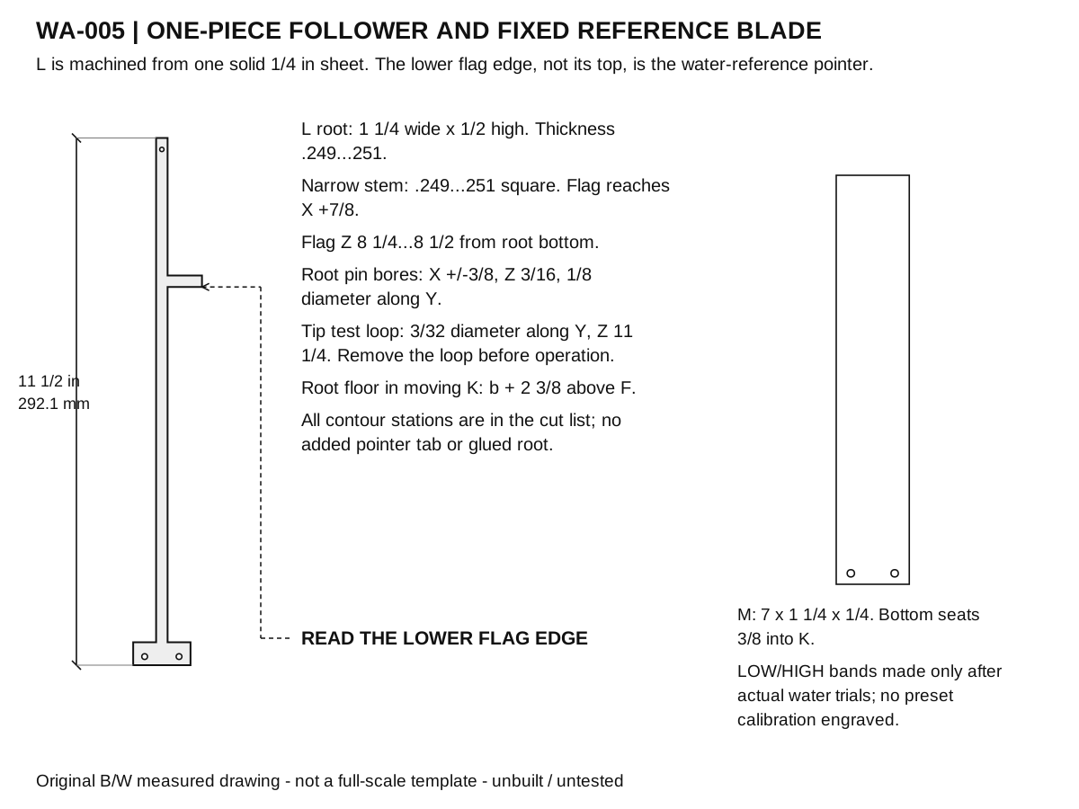
| L One-piece follower stem and flag | 1 | 11 1/2 in x 1 1/2 in x 1/4 in 292.1 x 38.1 x 6.35 mm | Solid unfilled HDPE, such as King StarBoard standard material machined from oversize stock to the actual gauge. No foamed core, adhesive joint or transferred food-contact certification. One retained XZ profile, all .249...251 in thick in Y. Relative to stem axis X 0 and root bottom Z 0, vertices: (-.625,0),(.625,0),(.625,.5),(.125,.5),(.125,8.25),(.875,8.25),(.875,8.5),(.125,8.5),(.125,11.5),(-.125,11.5),(-.125,.5),(-.625,.5). Straight stem width .249...251; root width 1.249..1.251. Root pin holes .125...126 along Y at X +/- .375, Z .1875. Temporary test-loop hole 3/32 in along Y at X 0, Z 11.25. The LOWER flag edge is the only reading edge. Root bottom square to the stem within .002 in over a 1 in reference. |
| M Blank fixed reference blade | 1 | 7 in x 1 1/4 in x 1/4 in 177.8 x 31.75 x 6.35 mm | Solid unfilled HDPE, such as King StarBoard standard material machined from oversize stock to the actual gauge. No foamed core, adhesive joint or transferred food-contact certification. Bottom square to blade axis within .002 in over 1 in; whole straightness within .002 in. Actual blade 7 Z by 1.25 X by .25 Y; receive width 1.249..1.251, thickness .249...251. Install X 13.375..14.625, Y 10.375..10.625, Z F+10.375..F+17.375. Two .125...126 in side-pin bores at local X .25/1.0, Z .1875. Lower .375 in enters K. Mark actual LOW/HIGH bands after qualification; no pre-calibrated ruler is supplied. |
US rule with 1/64 in divisions; calipers and depth gauge readable to .001 in; square and straightedge; .001 in feeler; straight 1/4 in square setup bar; clamped wood saw/drill; router or mill and square files for the HDPE pockets; 3/32, 1/8, 7/64, 3/16 and 13/64 in bits; countersink; small wrenches and 3/32 in hex key; suitable force balance and known reference; plain water, independent depth rule and water-resistant marking crayon. Complete receiving dimensions and repeated water trials govern.
x left/right; y along the apparatus; z upward. Fabrication datum and any separate operating tilt are stated in steps.
Retained segments with the same part/instance belong to one machined stock piece, not additional parts. Positions and sizes below are US inches; rotations are degrees.
| Part / instance | Origin x,y,z | Size / rotation |
|---|---|---|
| A / 1 | [0, 0, 0] | [24, 20, 0.75] / [0, 0, 0] |
| B / 1 | [10.25, 18, 0.75] | [3.5, 0.75, 18] / [0, 0, 0] |
| C / 1 | [10.25, 18.75, 0.75] | [0.75, 1.25, 4] / [0, 0, 0] |
| C / 2 | [13, 18.75, 0.75] | [0.75, 1.25, 4] / [0, 0, 0] |
| D / 1 | [11.25, 9.75, 7.5] | [1.5, 8.25, 0.75] / [0, 0, 0] |
| E / 1 | [11.25, 9.75, 10.5] | [3.5, 8.25, 0.75] / [0, 0, 0] |
| F / 1 | [11.25, 9, 7.5] | [1.5, 0.75, 0.75] / [0, 0, 0] |
| G / 1 | [11.25, 15, 5.5] | [1.5, 3, 2] / [0, 0, 0] |
| F / 2 | [11.25, 9, 10.5] | [1.5, 0.75, 0.75] / [0, 0, 0] |
| G / 2 | [11.25, 15, 8.5] | [1.5, 3, 2] / [0, 0, 0] |
| H / 1 | [10.5, 8.25, 1.75] | [3, 3, 0.125] / [0, 0, 0] |
| H / 2 | [10.5, 8.25, 3.875] | [3, 3, 0.125] / [0, 0, 0] |
| I / 1 | [10.5, 8.25, 1.875] | [3, 3, 2] / [0, 0, 0] |
| J / 1 | [10.75, 8.5, 1.875] | [0.25, 0.25, 2] / [0, 0, 0] |
| J / 2 | [10.75, 10.75, 1.875] | [0.25, 0.25, 2] / [0, 0, 0] |
| J / 3 | [13.0, 8.5, 1.875] | [0.25, 0.25, 2] / [0, 0, 0] |
| J / 4 | [13.0, 10.75, 1.875] | [0.25, 0.25, 2] / [0, 0, 0] |
| K / 1 | [11.25, 9.375, 4.0] | [1.5, 0.75, 0.5] / [0, 0, 0] |
| K / 2 | [13.25, 10.125, 11.25] | [1.5, 0.75, 0.5] / [0, 0, 0] |
| L / 1 | [11.375, 9.625, 4.125] | [1.5, 0.25, 11.5] / [0, 0, 0] |
| M / 1 | [13.375, 10.375, 11.375] | [1.25, 0.25, 7] / [0, 0, 0] |
Plain fresh nonpotable water, 40..95 F, in the received unmodified pan only. No drinking, food contact, detergents, fuels, brine, freezing or hot water.
Only the qualified LOW 1.5 in and HIGH 3.5 in bands are intended. Always check the water itself. No automatic filling, shutoff, overflow alarm or precise intermediate reading is claimed.
Keep A fully supported and pan/frame level. Attend filling and drawing; later qualified sessions last no more than 30 minutes, then drain and dry.
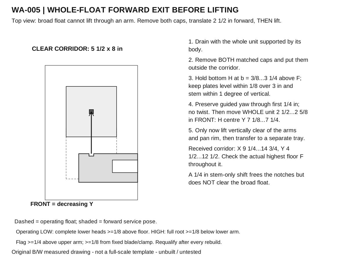
Do not carry a charged pan or frame with the float inside. Use the supported 2.5 in forward side-exit path before vertical removal. The flag is not a lifting handle.
Before use inspect the core, complete hardware, guide walls and marks. Stop for swelling, binding, changed wet mass, rubbing, unclear bands, loose caps or a changed pan/floor reference.
Drain and remove the whole group through the stated cap/translation/lift sequence before lifting the pan or opening the float. Do not pry the T root or flag through a closed guide.
Expose and clean every relief/spacer with the actual material maker instructions; do not rinse a closed charged assembly or use an unknown coating. Dry fully before storage. Replace failed materials instead of hiding damage.
Repeat complete wet mass, drag, motion and both real water-reference bands after changing any material, fastener, cleaning process or pan position. Calculations are conditional geometry and force budgets, not measured reliability, structural rating or physical test results.
F is the actual highest floor anywhere in the full service corridor, measured from A underside. Its accepted range is .875..1.125 in. Reference drawings use F = 1 and b = .75 only. b is the actual bottom H center underside above F, not water depth. Every floating b+... height is ABOVE actual F: its global Z from A underside is F+b+.... Drawing 04 local z is measured from bottom H underside. The published pan outer height is never used as its interior floor datum.
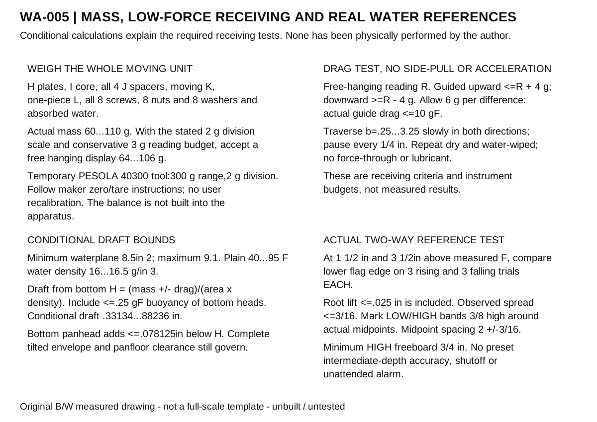
The actual 60..110 g moving-mass gate includes both plates, foam, four compression spacers, moving K, L, all eight moving screws/nuts/washers and water pickup. The 10 gF drag allowance includes the conservative instrument-difference budget. Typical foam and HDPE data are material-selection context, not an achieved mass result.
For received geometry, the lower foam waterplane is at least 8.5 in2; 9.1 in2 is a conservative upper bound including the permitted small tilt. Plain 40..95 F water is modeled at 16..16.5 g/in3. Up to .25 g equivalent buoyancy from the four below-plate heads is included in the shallowest-draft bound. Thus draft from bottom H is conditionally between (60-10-.25)/(9.1*16.5) = .33134 and (110+10)/(8.5*16) = .88236 in. These are not observed float depths.
The top-only foam reliefs start 1.5 in above the foam underside; the maximum modeled waterline remains lower. Hard J spacers set the plate separation. No hidden gasket, sealed air box, glued foam or specified leak-tight joint is assumed.
K pockets are close-fitting .252...254 by 1.252..1.254 in. Root-center lift is <=.025 in, and rocking is included. From the seated posture, continuous movement remains on the small-angle contact branch; the root cannot pass 10 degrees while engaged. Even at that provisional angle, .374-.025-hypot(1.251,.251)/2*sin(10 deg) > .23 in of full root section remains below the rim. With that conservative common section, solve w*cos(beta)+.23*sin(beta) <= pocket for each orthogonal projection, not a small-angle tangent approximation. The complete K/H and K/E bearing joints must stay flat within a .001 in feeler check, and root/blade bases must be square to their long axes within .002 over 1 in. Full receiving gates and hardware envelopes are checked separately; no perfectly fixed root is assumed.
The force/lift component of hysteresis is 2*10/(8.5*16) + .025 = .17206 in. This is NOT a bound on total flag-reading spread: guide tilt changes the height of the lateral flag and the long stem, and joint play may change during motion. The actual six-pass spread <=3/16 in at BOTH references is the decisive receiving gate. No wear, temperature, life or intermediate-depth accuracy is certified.
After both guide caps are removed, the whole unit translates 2.5..2.625 in forward before lifting, until the actual H plate center is at Y 7.125..7.25. Initial notch exit preserves the SAME yaw as in its matched closed guides; do not twist the square stem in the half-notches. Later handling holds stem within 1 degree of vertical, plates level within 1/8 over 3 in, and the original FRONT orientation without yawing. This clears the broad float from the main-arm fronts; freeing only the quarter-inch stem does not. The original 5.5 x 8 in received corridor includes that translation and the full float/hardware yaw/tilt envelope.
The original drawings, complete-body envelope audit, export retention and native-page review are documented separately. They establish editorial consistency within explicit receiving limits; they are not a physical prototype, strength, friction, buoyancy or calibration trial.
Rubbermaid Commercial Products: FG334900GRAY bus/utility box. Published outer 20 x 15 x 5 in, HDPE and 4.6 gal nominal capacity only. The full interior corridor, floor F, rim and operating fit are original actual receiving gates, not maker-provided internal dimensions. Source
Zotefoams: Plastazote LD45 PIS A013, Issue 1 Revision 1, June 2026. Closed-cell crosslinked PE context and typical density 45 kg/m3 only. Typical material data do not prove complete wet moving mass, life or actual buoyancy. Source
King Plastic: King StarBoard standard material sheet. Standard HDPE material context and typical density .955 g/cc. Nominal sheet gauges do not satisfy the original precision machining/receiving limits automatically. Source
USGS Water Science School: Water density. Plain-water density context supports the conservative 16..16.5 g/in3 budget over 40..95 F. This is not evidence of an actual water trial. Source
W. W. Grainger: 856YN8 / 1-ppm-4c-275 #4-40 x 2.75 in pan-head screw. Published 2.75 in under-head length, 7/32 in maximum pan-head diameter, 5/64 in maximum height and minimum 1.5 in threaded tail. Actual receiving remains required. Source
PESOLA: 40300 Medio Line 300 g / 2 g spring balance. 300 g range, 2 g divisions, +/- .3% precision and no user calibration. The larger original per-reading/difference budgets include reading and zero allowances. Source
PENCOM: Type B narrow washer catalog, printed page 102. Nominal #4 Type B narrow washer dimensions are .032 in thick, .125 ID and .250 OD. Complete eccentric envelope limits in this construction are original receiving gates. Source
Albany County Fasteners: #4-40 low-profile nylon-insert 316 stainless hex nut. Nominal .251 in across flats and .125 in height. Actual corner envelope, height and complete thread projection must be received; no substituted tall nut is covered. Source
JC Fasteners: ASME B18.3-1 SS316 socket-head cap screw table. Primary SS316 socket-cap table: #4-40 head maximum .183 D/.112 H and named 1 in / 1.75 in length candidates. The length codes are marked nonpreferred/limited availability; no current stock is promised. Original received maximum .185 D/.115 H and minimum .5 in full tip thread apply as actual receiving gates, not a catalog thread-length promise. No rated property is transferred. Source