WA-006 Submersion-primed service-water siphon with positive air-break parking
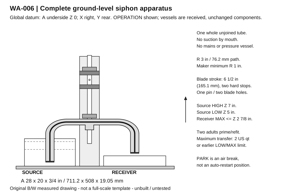
Transfer an attended small batch from a taller open source into a separate shallow receiver without lifting the loaded source, then expose the entire inlet to air by positively raising and pinning the complete unjoined siphon.
Original two-adult, attended, low-platform plain cold nonpotable service apparatus. No mains, pressurized vessel, potable treatment, unattended drain, automatic restart, flow or structural rating. This is an unbuilt/untested editorial design, not a completed fabrication or performed qualification. Unbuilt / untested. US customary dimensions control.
Before cutting
Receive the actual functional components before machining: the published outer dimensions do not prove vessel-cavity fit. Calipers, accurate routing/planing and measured receiving gates are needed; do not assume rough stock meets the tolerances.
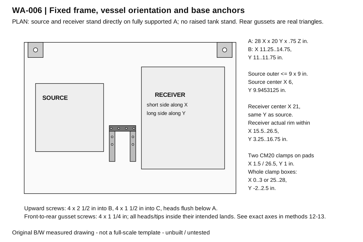
Global inches are measured from the front-left A UNDERSIDE: X right, Y rear, Z upward. All levels and hole coordinates in this guide use that SAME global datum unless explicitly called local. Source and receiver stand directly on A.
Plan for two adults during filled-tube installation, a stable fully supported/clamped base and a catch area that can contain the whole attended charge. No hand goes between cover/backplate or beneath a travel stop. Confirm actual working access for both adults; no standard hand-size or automatic fit is assumed.
Read the maker instructions supplied with the actual components. This guide uses a named continuous tube and unmodified vessels; it does not confer their regulatory approvals on the assembled apparatus.
Materials and actual cuts
Part
Quantity
Actual dimensions
Material / special cut
A Fully supported base
1
28 in x 20 in x 3/4 in 711.2 x 508.0 x 19.05 mm
Flat exterior-bond birch plywood, actual 3/4 in (19.05 mm) thick within .005 in (0.13 mm); seal exposed wood and let the finish cure before service. X 28, Y 20, Z .75. Four mast screws are installed upward and countersunk flush before the base is clamped to its support.
B Fixed mast
1
28 in x 3 1/2 in x 3/4 in 711.2 x 88.9 x 19.05 mm
Flat exterior-bond birch plywood, actual 3/4 in (19.05 mm) thick within .005 in (0.13 mm); seal exposed wood and let the finish cure before service. Length is vertical Z; width is X. Front plane Y 11, bottom Z .75. Keep the entire front sliding surface flat.
C Rear triangular mast gusset
2
6 in x 4 in x 3/4 in 152.4 x 101.6 x 19.05 mm
Flat exterior-bond birch plywood, actual 3/4 in (19.05 mm) thick within .005 in (0.13 mm); seal exposed wood and let the finish cure before service. Each raw 6 Z x 4 Y blank becomes a right triangle with vertices (Y, Z)=(11.75, .75), (15.75, .75), (11.75, 6.75). Thickness runs along X; make left and right pieces.
D Back-open guide block
2
3 1/2 in x 1 in x 7/8 in 88.9 x 25.4 x 22.225 mm
Straight-grained hard maple, planed to the actual finished section; no knots, splits, wax or oily finish on sliding/contact faces. X 3.5, Z 1, Y .875. Through-Z, back-open rectangular groove 25/32 in (.78125 /19.84 mm) wide and 17/32 in (.53125 /13.49 mm) deep; detail and actual receiving range in method 06.
E Moving blade and integral hand grip
1
22 1/2 in x 3/4 in x 1/2 in 571.5 x 19.05 x 12.7 mm
Straight-grained hard maple, planed to the actual finished section; no knots, splits, wax or oily finish on sliding/contact faces. Length Z, width X, thickness Y. Round only the top grip corners, radius 1/8 in (3.18 mm); preserve straight bearing faces. Two index holes and eight rear-flush bolt heads are detailed separately.
F Routed siphon bow with integral mounting tab
1
16 1/2 in x 11 1/4 in x 3/4 in 419.1 x 285.75 x 19.05 mm
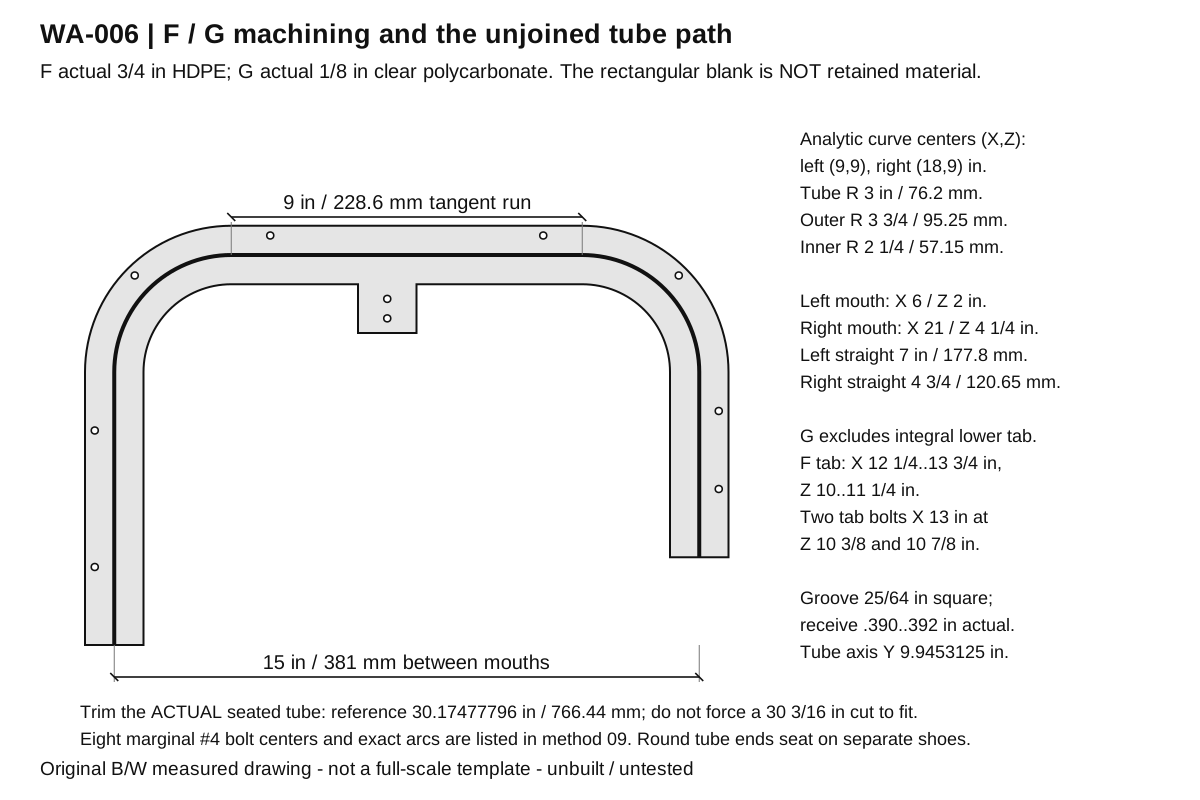
Virgin solid HDPE sheet, actual 3/4 in (19.05 mm) thick within .005 in (0.13 mm); machine without heat-forming, adhesive or welded joints. Raw rectangle X 5.25..21.75, Z 1.5..12.75 is a machining blank, not the retained profile. Cut the true U profile, lower ends at Z 2 and 4.25, plus the integral tab X 12.25..13.75/Z 10..11.25. Route the continuous 25/64 in groove from the front.
G Removable transparent U cover
1
16 1/2 in x 11 1/4 in x 1/8 in 419.1 x 285.75 x 3.175 mm
Clear solid polycarbonate sheet, actual 1/8 in (3.18 mm) thick within .005 in (0.13 mm); drill backed clearance holes, not self-tapping screws. Cut the same true U silhouette as F, WITHOUT its integral lower mounting tab. Ends terminate at the tube-mouth planes Z 2 and 4.25. Eight marginal retaining holes; keep the center passage visible.
H Positive travel stop
2
2 1/2 in x 1 in x 1/2 in 63.5 x 25.4 x 12.7 mm
Straight-grained hard maple, planed to the actual finished section; no knots, splits, wax or oily finish on sliding/contact faces. X 2.5, Z 1, Y .5. Lower moving stop origin Z 13; upper moving stop origin Z 25. Both bear on the fixed guides; do not substitute a friction stop.
J Removable annular end shoe
2
1 1/2 in x 1 1/2 in x 1 1/4 in 38.1 x 38.1 x 31.75 mm
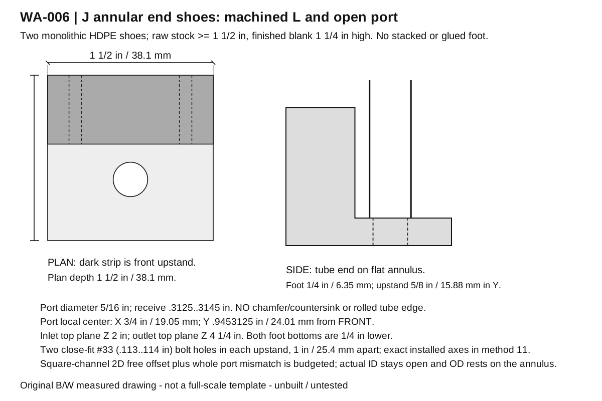
Virgin SOLID MONOLITHIC HDPE stock, raw at least 1.5 in (38.1 mm) thick and machined to the finished 1.25 in (31.75 mm) Z height. No laminated stack, adhesive or welded joint. Machine an L from each solid blank. Foot .25 in (6.35 mm) thick, 1.5 X x 1.5 Y. Front upstand is 1 in (25.4 mm) above foot and 5/8 in (15.88 mm) deep in Y. Remove the upper rear 7/8 in (22.23 mm) in Y. Drill a vertical 5/16 in port, no chamfer, centered X .75 from side and Y .9453125 from FRONT. Each shoe is one piece, not glued.
P Front clamp protection pad
2
2 in x 2 in x 1/8 in 50.8 x 50.8 x 3.175 mm
Flat hard maple or birch plywood, actual 1/8 in (3.18 mm) thick. Loose dry pads at front-left and front-right clamp seats. They protect the base; no padding under the vessels.
T Continuous unjoined siphon tube
1
31 in x 3/8 in x 1/16 in 787.4 x 9.525 x 1.5875 mm
Saint-Gobain Tygon Lab E-3603 ACF00017, nominal 1/4 in ID x 3/8 in OD x 1/16 in wall. Buy a length longer than 31 in (787.4 mm). Rough cut 31 in, then finish by the actual seated-groove method; reference centerline length 30.17477796 in (766.44 mm), about 30 3/16 in (766.76 mm). Width here is OD and thickness is wall, not a flat rectangular cut.
Hardware and tools
4 x Stainless #10 flat-head wood screw, 2 1/2 in (63.5 mm) long; major diameter <= .190 in, head OD <= .375 in. A upward into B; axes X 11.5, 12.5, 13.5, 14.5 / Y 11.375. Countersink flush at A underside; shank length includes head.
4 x Stainless #10 flat-head wood screw, 1 1/2 in (38.1 mm) long; same finite envelope. A upward into C: X 11.625 and 14.375, each at Y 12.5 and 13.5. Flat heads flush under A.
4 x Stainless #10 flat-head wood screw, 1 1/4 in (31.75 mm) long; same finite envelope. B front into C: X 11.75 and 14.25, each at Z 1.75 and 2.75; direction +Y from Y 11. Head flush to B front, away from blade.
4 x Stainless #10 pan-head wood screw, 1 1/2 in (38.1 mm) under head; major <=.190, head OD<=.375, head height<=.125 in. Two per D from Y 10.125 toward +Y, axes X 11.75/14.25 and Z 21/24.5. Through .875 in D, enter B about .625 in; no protrusion from B rear.
2 x Stainless #8-32 flat-head machine screw, 1 5/8 in (41.28 mm) overall length; major<=.164, head OD<=.3125, head cone/height<=.100 in. E rear at Y 11 toward -Y through E .5 and F .75, axes X 13/Z 10.375 and 10.875. Head flush to rear of E; nut/washer in front of F on the integral tab, clear of G.
4 x Stainless #8-32 flat-head machine screw, 1 1/2 in (38.1 mm) overall length; same finite head/shank envelope. Two per H, E rear to -Y: X 13 and Z 13.25/13.75, 25.25/25.75. Head flush rear E, through E .5 + H .5.
6 x Stainless #8 flat washer, OD .375 in maximum, .028-.035 in thick; hole accepts #8 shank. One under each #8 nut at front of F/H; receive full OD, not nominal broad-washer size.
6 x Stainless #8-32 hex nut, AF<=.344 in, across-corners<=.400 in, thickness .125-.140 in. One per #8 bolt. At least two full threads beyond the complete nut; visible tail <=.375 in and burr-free. Front nuts remain accessible; no hand grip on threaded ends.
8 x Stainless #4-40 socket-head machine screw, 1 1/8 in (28.58 mm) under head; major<=.112, head OD<=.185, head height<=.115 in. G front Y 9.625 toward +Y through G .125 + F .75, at the eight outer-margin centers listed in method 09. No screw, washer or nut crosses the tube groove.
4 x Stainless #4-40 socket-head machine screw, 1 3/4 in (44.45 mm) under head; same finite envelope. Two per J from Y 9 toward +Y through J upstand .625 + G .125 + F .75 =1.5 in; axes left X 5.5/6.5, Z 2.5 and right X 20.5/21.5, Z 4.75.
12 x Stainless #4 flat washer, OD .250 in maximum, thickness .028-.035 in. One behind F under every #4 nut. Require .120-.130 in hole receiving #4 thread.
12 x Stainless #4-40 hex nut, AF<=.251 in, across-corners<=.290 in, thickness .120-.130 in. One per #4 bolt, rear of F. Every bolt is fully threaded through nut; tail .060-.150 in for cover bolts and .060-.150 in for shoe bolts. Loose hardware collected in a tray during priming.
1 x Stainless clevis pin, actual diameter .249-.250 in, under-head length 2 in +/-1/64, head OD<=.500 /height<=.125 in; cross-hole center 1 3/4 in from under-head, hole .070-.080 in. Insert from rear Y 11.75 toward -Y through B and E. Pin tip around Y 9.75; cross-hole around Y 10.0. No substituted threaded pin or protruding ball detent.
1 x Stainless split cotter, .0625 in maximum diameter, usable length 1/2 in; installed complete envelope within .5 in diameter about pin cross-hole and .25 in along Y. Pass through clevis cross-hole and spread both legs sufficiently for retention without sharp exposed tips. Reuse only if maker permits; keep a spare. No loose washer on the pin.
2 x BESSEY CM20 C-clamp, received usable opening at least 1 7/8 in, throat at least 1 3/8 in. Clamp base+P pads to a stable fully supporting low work platform .5-.75 in thick at X 1.5 and 26.5/Y 1. Entire tool including handle sweep confined to its separate front corner keep-out box; no maker clamping-force rating transferred.
Table or track saw, backed jigsaw, router with controlled templates and depth stops, sharp chisels, drill press or square drill guide, 1/8, 3/16, 13/64, 1/4, 17/64, number 33 (.113 in) and 5/16 in drills, actual-head countersink, calipers, straightedge, square, depth gauge, .002 in feeler, ruler, clean tube cutter, clamps, sockets/hex keys, measured jug and catch tray.
Measured assembly reference
Global inches: X left/right, Y front/rear, Z up from A underside; scene shows OPERATION. Moving E/F/G/H/J and their hardware translate +Z 6.5 in to PARK. Triangle/U/removed-notch entries are machined profiles, NEVER solid envelope boxes.
Retained segments with the same part/instance belong to one machined stock piece, not additional parts. Positions and sizes below are US inches; rotations are degrees.
Part / instance
Origin x,y,z
Size / rotation
A / 1
[0, 0, 0]
[28, 20, 0.75] / [0, 0, 0]
B / 1
[11.25, 11, 0.75]
[3.5, 0.75, 28] / [0, 0, 0]
C / 1
[11.25, 11.75, 0.75]
[0.75, 4, 6] / [0, 0, 0]
C / 2
[14, 11.75, 0.75]
[0.75, 4, 6] / [0, 0, 0]
D / 1
[11.25, 10.125, 20.5]
[3.5, 0.875, 1] / [0, 0, 0]
D / 2
[11.25, 10.125, 24]
[3.5, 0.875, 1] / [0, 0, 0]
E / 1
[12.625, 10.5, 6.5]
[0.75, 0.5, 22.5] / [0, 0, 0]
F / 1
[5.25, 9.75, 2]
[16.5, 0.75, 10.75] / [0, 0, 0]
G / 1
[5.25, 9.625, 2]
[16.5, 0.125, 10.75] / [0, 0, 0]
H / 1
[11.75, 10, 13]
[2.5, 0.5, 1] / [0, 0, 0]
H / 2
[11.75, 10, 25]
[2.5, 0.5, 1] / [0, 0, 0]
J / 1
[5.25, 9, 1.75]
[1.5, 1.5, 0.25] / [0, 0, 0]
J / 1
[5.25, 9, 2]
[1.5, 0.625, 1] / [0, 0, 0]
J / 2
[20.25, 9, 4.0]
[1.5, 1.5, 0.25] / [0, 0, 0]
J / 2
[20.25, 9, 4.25]
[1.5, 0.625, 1] / [0, 0, 0]
P / 1
[0.5, 0, 0.75]
[2, 2, 0.125] / [0, 0, 0]
P / 2
[25.5, 0, 0.75]
[2, 2, 0.125] / [0, 0, 0]
Numbered assembly
Identify the setup before buying. This is an attended cold plain service-water transfer, not a drinking-water device or an automatic drain. A useful run ends at the first of 2 US qt (1.89 L) transferred, source LOW, or receiver MAX. The working source surface is global Z 5..7 in (127 to 177.8 mm); the nominal outlet mouth is Z 4 1/4 in (107.95 mm). No minimum flow, duration or automatic restart is specified. Read all eight plates, then receive the purchased parts and vessel cavities before machining the wooden frame.
Receive the actual Tygon ACF00017 tube. Measure several uncompressed sections: OD .373-.377 in (9.47 to 9.58 mm), ID .247-.253 in (6.27 to 6.43 mm), no ovality, cuts or collapsed regions. These are original fit gates, not the manufacturer tolerance. Make a smooth temporary horizontal coil with centerline radius at least 3 in (76.2 mm); its maximum outside diameter is about 6.38 in (162.1 mm). The actual source must take that whole loose coil below water with at least 6 1/2 in (165.1 mm) unobstructed horizontal clearance and enough depth for loosely stacked turns. Do not use hot water or force a kink to make it fit.
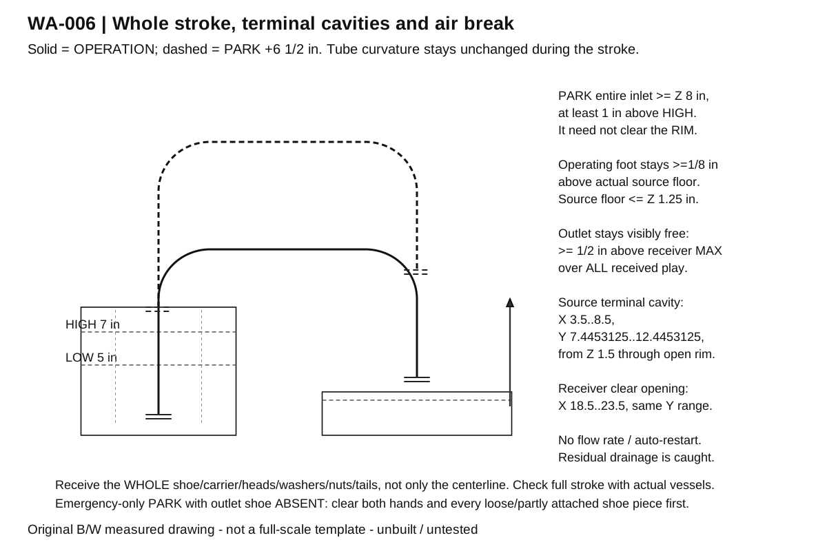
Receive both unchanged vessels on a flat reference board at the intended .75 in (19.05 mm) base height. Center the source at X 6/Y 9.9453125 in (152.4/252.61 mm); its outer X/Y envelope must be no larger than 9 x 9 in (228.6 x 228.6 mm), actual floor no higher than Z 1.25 in (31.75 mm), and open rim between Z 7.75 and 8.5 in (196.85 to 215.9 mm). Its clear cavity must contain X 3.5..8.5/Y 7.4453125..12.4453125 in (88.9 to 215.9/189.11 to 316.11 mm) from Z 1.5 through the open rim; verify the curved/tapered sides, not only the top opening. Make removable level marks at global Z 5 and 7 in. Actual source capacity below HIGH governs; measure its charge, never more than 6 US qt (5.68 L), and do not equate maker 6 qt with the useful transfer amount. Surround the fully supported platform with a catch area that contains at least 2 US gal (7.57 L), more than the whole charged water quantity.
Orient the receiver with its SHORT nominal 10 7/16 in (265.11 mm) side along X and LONG 12 3/4 in (323.85 mm) side along Y, center X 21/Y 9.9453125 in (533.4/252.61 mm). Actual complete rim must lie within X 15.5..26.5/Y 3.25..16.75 in (393.7 to 673.1/82.55 to 425.45 mm), rim Z no higher than 3.375 in (85.73 mm). Its open inner region X 18.5..23.5/Y 7.4453125..12.4453125 in (469.9 to 596.9/189.11 to 316.11 mm) must remain unobstructed at the rim and MAX waterline. Set MAX at least .5 in (12.7 mm) below its lowest rim and no higher than global Z 2.875 in (73.03 mm). Using a separate measured jug, verify at least 2.5 US qt (2.37 L) reserve from empty to MAX. With the pan EMPTY, also receive the complete 2 x 2 x 2 in (50.8 mm cube) thumb-withdrawal corridor directly below the outlet, X 20..22/Y 8.9453125..10.9453125/Z 2.25..4.25 in, with no wall, floor, clamp or loose part in it. Empty again. A maker outer size or nominal capacity alone does not satisfy these conditions.
Cut A/B and the two C gussets with the finished dimensions in the table. For each C, mark the right triangle on its broad Y/Z face; cut off the diagonal waste and smooth the long sloping edge. Keep the vertical leg against B, the 4 in (101.6 mm) leg on A, and thickness along X. Seal exposed plywood, keep the mast front flat, and let the finish cure. Round nonbearing external edges to about 1/16 in (1.59 mm); do not round screw lands or guide contacts.
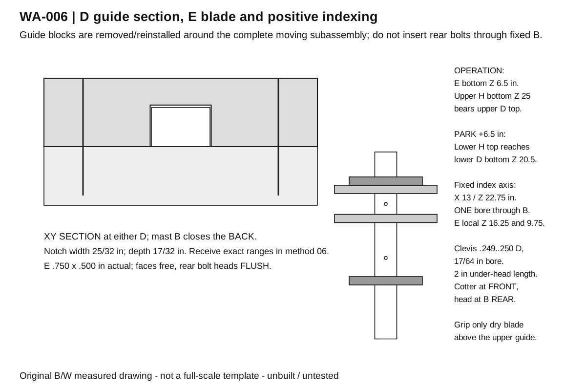
Plane E to .750 x .500 in (19.05 x 12.7 mm), each within .005 in (0.13 mm); straightness/parallel-face departure must be no more than .005 in over its 22.5 in (571.5 mm) length. Machine D from its BACK: remove the centered .78125 in (19.84 mm) wide by .53125 in (13.49 mm) deep rectangular notch, fully through its 1 in (25.4 mm) Z height. Receive notch width .78125-.78325 in and depth .53125-.53325 in. Square corners with a chisel; no leftover router radius may push E forward. With the back closed by a flat scrap mast, E must slide freely without rocking out or binding. The small clearance is intentional; this needs accurate planing/routing and calipers, not ordinary rough lumber.
Lay out F and G from the global X/Z coordinate profile on plate 02. The tube centerline rises at X 6 to Z 9, follows a quarter-circle R 3 about (9, 9), runs horizontally at Z 12 from X 9 to 18, follows R 3 about (18, 9), then descends at X 21 to its outlet. Outer arcs are R 3.75 in (95.25 mm), inner arcs R 2.25 in (57.15 mm); each straight leg is 1.5 in (38.1 mm) wide. F includes the solid lower mounting tab X 12.25..13.75/Z 10..11.25 in. G has only the U, no tab. Left lower edge is Z 2, right lower edge Z 4.25. Cut actual smooth arcs, not stepped bounding rectangles. Keep all cut edges square to the broad face. For ordinary wood-screw axes, receive center positions within .005 in (0.13 mm) and drilling directions within .25 degree of the stated direction; tighter explicitly stated terminal/guide gates still govern.
Route the continuous groove into F from its front plane Y 9.75 in (247.65 mm). Use multiple shallow passes along the exact centerline: width and depth 25/64 in (.390625 in /9.92 mm), actual width/depth .390-.392 in (9.91 to 9.96 mm), center location within .002 in (0.05 mm) at the terminals. End the groove square through both lower end faces. Remaining back thickness must be at least .338 in (8.59 mm). Smooth tool marks without enlarging the terminal guide. With actual tube laid in place, the bore must remain round and visibly open; no compression is used to hold it. The original curve is much gentler than the maker 1 in minimum: receive the complete fitted axis with no local bend tighter than 2.75 in (69.85 mm), including the last inch at each mouth.
Drill the eight G/F marginal holes as a backed stack, 1/8 in (3.18 mm) clear through. Centers(X, Z), in inches, are (5.5, 4), (5.5, 7.5), (6.525126, 11.474874), (10, 12.5), (17, 12.5), (20.474874, 11.474874), (21.5, 6), (21.5, 8). The diagonal centers are R 3.5 in (88.9 mm) from the respective arc centers at 135 and 45 degrees. Keep each center within .005 in (0.13 mm). Fit #4 bolts from the front of G; washers and nuts are behind F. The complete washer OD is no larger than 1/4 in. Do not let an oversize washer bridge the open inner profile, groove or blade.
Machine the two J shoes from solid HDPE as plate 03 shows. Each foot is 1.5 X x 1.5 Y x .25 Z in (38.1 x 38.1 x 6.35 mm); the front upstand is .625 in (15.88 mm) deep and 1 in (25.4 mm) above the foot. Upper rear waste is removed square. For the inlet shoe, front Y 9, foot top Z 2, left X 5.25; for outlet, front Y 9, foot top Z 4.25, left X 20.25. Drill the vertical port at local X.75/Y .9453125 in, actual diameter .3125-.3145 in (7.94 to 7.99 mm), as-assembled center within .006 in (0.15 mm) radially of the nominal groove terminal center, INCLUDING machining, bolt play and its complete tilted shank; do not use nominal bolt axes as proof. Keep the top annulus flat within .002 in and square to the channel; NO countersink or chamfer at that port. Ease only the outer shoe edges. The shoe is a mechanical end stop with an open port, not a sealed tube fitting or a calibrated orifice.
With G seated flat to F, temporarily bring each J upstand against G front and slide the foot under its matching lower end. Shoe front is Y 9 in (228.6 mm), upstand back Y 9.625; its foot reaches Y 10.5 beneath the complete terminal. Mark and drill two number 33 (.113 in /2.87 mm) close-fit holes through J/G/F at inlet X 5.5/6.5, Z 2.5 and outlet X 20.5/21.5, Z 4.75 in (139.7/165.1 and 520.7/546.1;Z 63.5/120.65 mm). Use #4 x 1.75 in bolts from shoe front, washers/nuts behind F. Receive shoe-bolt major diameter .110-.112 in (2.79 to 2.84 mm) and these holes .113-.114 in (2.87 to 2.9 mm); all four through the matched stack. Both bolts are entirely outside the groove and vertical port. Fit each shoe without any rocking, flexed foot or forced shift of G. A .002 in feeler must not enter under a seated tube end on either side of its annular support during the later actual fit.
Lay A underside upward. Locate B on the opposite face at X 11.25..14.75/Y 11..11.75/Z .75 in. Drill 13/64 in (5.16 mm) clearance through A at its four mast axes, countersink the actual flat heads flush, then drill 1/8 in (3.18 mm) pilots into B. For ALL receiving pilots in methods 12-14, measure the actual drill point length p from its tip to the first full 1/8 in diameter; p must be<=.040 in (1.02 mm). The depth specified below is FULL CYLINDRICAL bore length INTO the receiving wood, held within 1/128 in (0.2 mm). If the stop collar contacts the outside clearance part, set total tip projection to its ACTUAL measured thickness plus the stated receiving depth plus p. Confirm on a matching scrap cut open before drilling the thin mast. For these four WB pilots, use 1 7/8 in (47.63 mm) receiving depth from B bottom: even the shortest accepted cylinder 1.8671875 in exceeds worst screw penetration 1.770625 in. Including maximum point/stop error, penetration is<=1.9228125 in into B, leaving at least 26.0721875 in (662.23 mm) of its minimum 27.995 in length. Screw A to B with four 2.5 in screws, keeping B square in both directions: departure from perpendicular is no more than 1/32 in (0.79 mm) over 28 in (711.2 mm). Do not drive screws so deeply that A underside becomes dished. All tips stay in B; the base underside must sit completely flat on its support.
Add C at left X 11.25..12 and right X 14..14.75 in, with the vertical legs against B rear Y 11.75. From A underside, drill clearance/countersink at X 11.625/14.375 and Y 12.5/13.5, then 1/8 in pilots into the thick part of each triangle. For WCbase use 7/8 in (22.23 mm) full-cylinder receiving depth from C bottom, adding actual A thickness and point p to the collar projection. Confirm at least 2 1/2 in (63.5 mm) solid receiving depth along the WHOLE pilot band before drilling the sloping triangle. The shortest accepted cylinder .8671875 in exceeds worst screw penetration .770625 in; maximum cylinder+point+.0078125 in stop error is .9228125 in, leaving at least 1.5771875 in (40.06 mm) solid wood. Fit four 1.5 in screws. Through B front at X 11.75/14.25 (offset from the upward mast screws) and Z 1.75/2.75, use backed clearance through B, then WCfront pilots 5/8 in (15.88 mm) full-cylinder receiving depth from C front, adding actual B thickness and point p to the collar projection. Confirm at least 2 in (50.8 mm) receiving depth along the whole pilot band at BOTH Z levels. Shortest cylinder .6171875 in exceeds worst screw penetration .520625 in; deepest point including stop error is .6728125 in, leaving at least 1.3271875 in (33.71 mm) solid wood. Fit four 1.25 in flat-head screws into C. Their front heads must be flush; C is not a hollow corner bracket. Recheck B square and every diagonal edge contains its screw tip.
Hold D against B front: lower block origin X 11.25/Y 10.125/Z 20.5; upper block same X/Y at Z 24 in. Both notches open BACK against B and share the same centered guide axis. Use E as a free sliding alignment gauge, with no screws or stops fitted yet. Relative notch center departure over the 4.5 in (114.3 mm) overall bearing span must be <=.005 in (0.13 mm); faces remain parallel to B. Drill 13/64 in clearance through D and 1/8 in WD receiving pilots into B at X 11.75/14.25 and Z 21/24.5. WD full-cylinder receiving depth is 43/64 in (.671875 in /17.07 mm) from B FRONT; collar tip projection is ACTUAL D thickness plus .671875 in plus measured point p<=.040 in. Keep the same 1/128 in depth accuracy. Measure actual D thickness .870-.880 in (22.1 to 22.35 mm) and B thickness at least .745 in (18.92 mm). With screw length up to 1.515625 in and D as thin as .870 in, maximum screw penetration is .645625 in; shortest accepted cylinder .6640625 in extends .0184375 in (0.47 mm) beyond it. Deepest pilot point is .671875+.0078125+.040=.7196875 in, less than actual B thickness>=.745 in: at least .0253125 in (0.64 mm) remains unpierced at the back. Measure B thickness and reset the stop if this reserve is not present; do not borrow the deeper WCbase setting for these screws. Fit four 1.5 in pan-head screws, stopping with full head contact, not crushed guide stock. Remove E and check no rear screw tip is exposed. These guide positions are now established; remove both D blocks again for the moving subassembly installation below, keeping their screws with them.
Assemble the moving parts on the BENCH with both D blocks removed from B. E OPERATION bottom will be global Z 6.5 and top 29 in (165.1/736.6 mm), front Y 10.5/rear Y 11. Use the global OPERATION layout on that separate bench to position F back Y 10.5 against E front. At X 13 and Z 10.375/10.875 in (330.2/263.53 and 276.23 mm), drill 3/16 in (4.76 mm) clearance through E/F and countersink from E REAR just to seat the #8 flat heads flush. Fit the two 1.625 in bolts from rear, then front washers/nuts on F tab. Nuts and their complete tails are below the U cover, not through it. Do not let a rear head protrude into the fixed mast sliding plane. With E held square at its stated OPERATION bench coordinates, receive three noncollinear F reference centerline points (X, Y, Z)=(6, 9.9453125, 2), (21, 9.9453125, 4.25), (9, 9.9453125, 12) in, each coordinate within .010 in (0.25 mm) of its layout. These control the clamped F-to-E orientation; tighten and recheck instead of treating loose 3/16 in bolt-hole axes as alignment. No operating movement at this fully tightened joint is permitted.
Fit the two H blocks on E FRONT, back Y 10.5/front Y 10 in. Their X interval is 11.75..14.25. Upper H origin Z 25, lower H origin Z 13 in. Use two #8 x 1.5 in rear-flush bolts at X 13/Z 25.25, 25.75 and 13.25, 13.75;3/16 in clearance, backed flush countersinks at E rear, washers/nuts on H front. With both adults supporting the complete moving subassembly at its OPERATION marks against B, reinstall the two D blocks AROUND E at their established positions; their side screws are reachable from the front, outside E. Do not try to pass an already stopped blade through closed guides or insert rear bolts through B. Upper H underside now bears on the solid FRONT STRIP of upper D top at Z 25: this is OPERATION. The intended bearing is the overlapping front strip, not the whole .5 in depth of H. Raise slowly until lower H top bears on the corresponding lower D front strip at Z 20.5: this is PARK, 6.5 in (165.1 mm) above OPERATION. Both guides retain all of E throughout. Receive the actual stop-to-stop stroke 6.5 in within 1/16 in (165.1 within 1.59 mm); nominal stop dimensions do not replace the final full-mouth level gates. The stops are not lifting points; never pull against an engaged stop.
With E resting on the OPERATION stop, drill the 1/4 in pilot then 17/64 in (6.75 mm) final index bore square along Y at global X 13/Z 22.75 in (330.2/577.85 mm), through B and E as one supported stack. Deburr without a large entry chamfer. Raise to the PARK stop and use the SAME B bore to mark/drill the second E bore; do not drill a second B hole. E local hole centers are nominal 16.25 and 9.75 in above its lower end. Receive both bores .265625-.267625 in (6.75 to 6.8 mm), axes within .005 in; the actual pin must insert fully without levering either stop. Pin is inserted from B REAR, cotter at the exposed FRONT cross-hole. Fit the whole cotter and spread its legs away from the hand grip.
Before wet use, qualify the entire empty stroke and all access. Withdraw the cotter and pin only while holding the dry upper blade at Z 27..29 in in OPERATION; keep fingers above the upper guide and away from all stop faces. Lift 6.5 in to PARK, let the stop bear, insert pin and cotter, then reverse. Never leave the blade between positions. Complete body/hardware, not only tube centerline, must stay clear of both actual vessels, mast, clamps and support over the entire movement. Retain the guide fit and no-contact conditions in the checks; if a stop, bolt head or nut catches, stop and correct the machining rather than force it.
Trial-fit and trim the tube DRY. Install both shoes and lay the 31 in rough tube into F with G removed. Seat the inlet end square on its annulus, without pushing it into the 5/16 in port. Follow the smooth channel and mark the outlet flush with its own shoe annulus; remove and make a square clean cut, with the cut endplane within .5 degree of perpendicular to the local straight tube axis. The later .002 in end-to-foot feeler gate controls its installed seating; do not substitute an oblique cut to disguise a curled terminal. Reference path is 30.17477796 in (766.44 mm), but the received groove/tube determines the final cut. Do not force the nominal 30 3/16 in cut into the shorter path. Refit so both ends rest fully and remain round, with no axial compression, stretch, kink or local tight bend; actual trimmed length must be 30.10..30.25 in (764.54 to 768.35 mm) and endpoints within .03 in (0.76 mm) of the stated planes. Neither end may curl or roll through its port. If these conditions conflict, remake the inaccurate groove or tube; do not add a splice.
Fit G and its eight independent retainers, then both J shoes. Verify the full terminal bore can be seen through each shoe port with no edge obstructing the tube ID; no tube wall is pinched between G/F. The .3125-.3145 in port must remain larger than the complete offset tube bore yet smaller than the complete offset OD. Actual no-contact/annular criteria, not nominal catalog sizes, govern. Move the WATER-FILLED tube through the empty-vessel setup in both locked positions and the continuous stroke: no end slippage, protrusion below a shoe, kinks, bubbles entering through damaged tube, lifted foot or loose cover. This receiving trial is required of a builder; it has NOT been performed by the author.
Install the whole base on a stable low work platform, no more than 12 in (304.8 mm) above the surrounding catch area; A is fully supported, not cantilevered. Platform top is .5-.75 in (12.7 to 19.05 mm) thick with its front edge aligned to A front. Put P pads at X .5..2.5 and 25.5..27.5/Y 0..2. Fit the two received CM20 clamps at X 1.5/26.5, Y 1, gripping A+pad+platform: maximum 1.625 in (41.28 mm) stack leaves at least .25 in (6.35 mm) reserve in the received 1.875 in opening. Receive the WHOLE clamp/handle in its front corner box, X 0..3 or 25..28, Y-2..2.5, Z-6..2.5 in. Keep both vessels and every moving part outside those boxes. No handle extension or claimed clamp force; stop if the base lifts, twists or the guide binds.
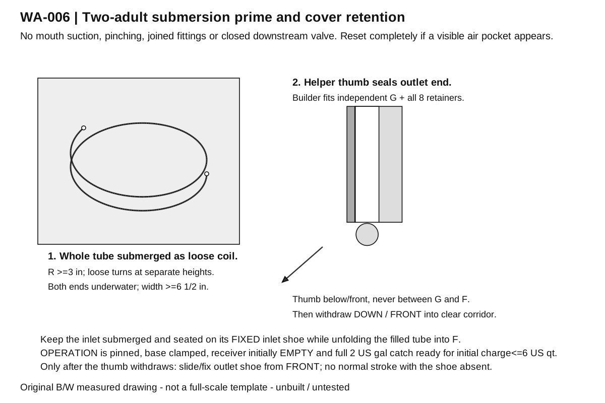
Prepare the attended priming session with TWO adults and a clear spill catch. Lock OPERATION with its pin/cotter; verify the source at HIGH, receiver EMPTY with its reserve, outlet over its received opening, and G/F already aligned. Remove G and ONLY the outlet shoe; keep the inlet shoe fitted. Put all removable nuts/bolts into a tray. Remove the tube and submerge its WHOLE length in a loose horizontal coil of radius>=3 in inside the source. Roll and lift sections UNDER water until the transparent tube has no visible trapped air; both open ends remain submerged. Access the loose ends through the open center of the coil, not by forcing fingers between its outside and the source wall; the received operators must be able to support and unfold it from the clear FRONT working aisle. Never suck, blow, connect a tap, pinch the tube shut or use a closed valve to fill it.
The helper keeps the inlet under water and places a clean gloved THUMB over the open outlet end itself while it is still submerged. Keeping the thumb seal, the helper lifts and unfolds the filled tube without any local radius below 3 in, supporting its straight portions with the free hand. The builder guides the inlet back down the open channel until its end rests on the fitted inlet annulus, then lays the filled path in F. Keep the helper thumb BELOW the outlet end, approached from the front; no finger is between G and F or across a retaining hole. If an end empties or a bubble appears, return the whole tube to the source and repeat rather than promise it will restart.
While the helper maintains the thumb seal and supports the outlet from below/front, the builder refits G and all eight marginal bolts/washers/nuts. Use hand tools away from the hose; no tube end is squeezed. The entire path including both last-inch terminal guides is now laterally closed and visible. The builder verifies the source inlet remains seated, the free outlet mouth is centered over the receiver and the helper can withdraw straight DOWN and FRONT into a clear 2 x 2 x 2 in (50.8 mm cube) hand corridor below the outlet. Neither adult moves the carriage or places a hand under a stop. All outlet-shoe fastening hardware is ready to the side, outside the stream path.
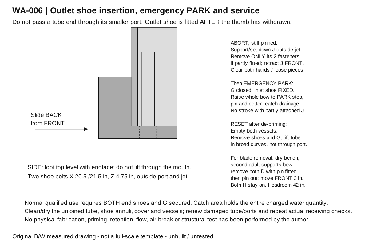
The helper now withdraws the thumb DOWN/FRONT, allowing the initial water to discharge into the receiver. This is still the attended installation trial: do NOT make a normal operating stroke with the outlet shoe absent; only the explicitly received emergency PARK below is permitted. From the FRONT, the builder slides the outlet L horizontally backward into place, its foot TOP already level with the tube-end plane, so the foot slides underneath the end and its port aligns with the bore. Do not lift the foot up through the endface or put a finger into the stream. Fit both outlet-shoe bolts at X 20.5/21.5, away from the central port, then washers/nuts behind F. If an air pocket enters, the end curls, the stream leaves the receiver, hardware is inaccessible or the foot does not seat freely, set the shoe down or support it from its front, outside the bore/stream. If either of its TWO shoe fasteners has been started, remove only those two; retract J completely FRONT, collecting the bolts/nuts in the tray. The full 2 US gal catch is already in place for the entire initial source charge<=6 US qt, with receiver initially empty; no removal time or flow duration is promised. Once J and all hands are outside the moving envelope, the builder may perform an EMERGENCY PARK with cover CLOSED and inlet shoe still FIXED: hold the upper blade, remove pin/cotter, raise 6.5 in to the PARK stop and repin/cotter. This emergency-only stroke is received with outlet shoe ABSENT; no stroke with a loose/partly attached shoe. Inlet shoe still bounds the entire inlet mouth above HIGH, while the absent outlet shoe creates a smaller envelope. Catch residual drainage, then open/clean/reset and repeat the whole prime. Do not present this emergency state as qualified transfer with a missing foot.
Once BOTH shoes and the cover are secure, observe the useful trial without assigning a flow rate. The tube must remain full, ends round and supported, both mouths unobstructed and discharge visibly free above receiver MAX. Watch source LOW, receiver MAX and transferred amount continuously; never leave it unattended. At the first limit or any fault, hold the upper dry blade, remove cotter/pin, lift the entire bow 6.5 in to PARK without twisting, let the PARK travel stop bear, then insert pin/cotter fully. The entire inlet mouth must now be at least 1 in (25.4 mm) ABOVE source HIGH and remain openly exposed to air, even at worst received play. It need not be above the source rim. Water may drain from the outlet after de-priming; the separate receiver must catch it.
Confirm the air break with the actual clear tube: air must enter at the exposed inlet and interrupt the liquid column. Do not interpret a slow stream as proof of an air break; do not reimmerse the inlet to try to restart. If the whole mouth is not clearly above HIGH, or flow/column does not break, remove the source from the inlet region and drain the loose tube into the catch after opening the cover. Leave the apparatus out of service until corrected. A successful qualification includes repeated prime, useful transfer, PARK air break and controlled residual drainage with the actual received parts; none is claimed as a test performed for this manual.
For service, leave PARK pinned, empty both vessels before moving them, and collect residual drips. Remove the two shoes and independent cover before lifting the tube clear; give it a 3 in minimum-radius path and keep loose hardware out of vessels. Never pull a tube end through its smaller shoe port. The removable bow may remain on its blade. For deep guide service, keep PARK pinned and have the second adult support E/F/H with both hands on dry wood, not the tube. Remove BOTH D guide blocks by their four accessible FRONT screws while the pin still retains the subassembly. Remove pin/cotter only after both adults have positive support, then translate the WHOLE E/F/H subassembly 3 in (76.2 mm) straight FRONT and lay it on a dry bench. The empty vessels, shoes and cover have already been removed; receive the complete frontward corridor, not just E. Require 42 in (1066.8 mm) overhead for this supported translation. Do NOT lift E over the upper guide: that would require more headroom. Refit D around the held blade and restore pin/cotter before releasing support; both H stops stay installed.
After every session, wash the dedicated plain-service tube and vessel surfaces according to the bought-component maker instructions applicable to the supplied material, rinse with service water, then drain and dry completely with generous curves. Do not transfer any maker chemical-resistance table into a home cleaning recipe. Inspect the transparent hose for clouding, flattening, cracks and rim cuts; replace damaged tube with the same identified product and repeat receiving/trim/prime checks. Inspect annular feet for edge roll, hole enlargement, cracks or rocking; remake a changed shoe, not an oversized port. Recheck rear flush heads, all nuts, cotter, dry guide fit, level marks and base clamps before the next use.
Checks
Procurement gate: actual tube ID/OD, coil clearance and received vessel floor/rim/whole-body cavity meet methods 02-04. Containers remain unmodified and open. Water is plain cold nonpotable service water only.
Machining gate: full real U arcs and integral tab match plate 02; no solid bounding-box backing is left in a vessel path. The minimum receiving radius of 2.75 in is larger than the maker 1 in minimum. Both terminals are guided to the actual flat endface planes.
Annular gate: with OD min .373, channel max .392, free radial offset in the square channel is sqrt(2)*(.392-.373)/2=.01343503 in; adding the complete received radial shoe-port mismatch<=.006 in gives .01943503 in. OD support margin is (.373-.3145)/2-.01943503=.00981497 in (0.25 mm). Bore opening margin is (.3125-.253)/2-.01943503=.01031497 in (0.26 mm). These geometric margins require uncompressed round ends and the received port/no-chamfer conditions; they are not a material-deformation or flow test.
Continuous motion gate: E remains in both fixed guides at every height, rear countersinks are flush, both hard stops seat without rocking on their defined front bearing strips, and each locked pin/cotter fits without forcing. Receive no tube/carrier/finite-hardware contact with actual source/receiver/clamps anywhere in the 6.5 in stroke, including guide play and yaw. The complete inlet shoe and its hardware must pass the received 5 x 5 in cavity.
Level gate: with all received play, complete inlet endface in PARK is>=Z 8 in (203.2 mm), at least 1 in above source HIGH 7. Complete operating inlet/foot stays>=.125 in above the ACTUAL source floor. Operating discharge is>=.5 in (12.7 mm) above receiver MAX and always visibly open. Highest source level is a water datum, not the rim.
Hands and service gate: two adults can support/unfold the filled tube without pinching, maintain the outlet thumb seal while the complete independent cover is fitted, withdraw the thumb clear, and slide/fix the outlet foot entirely from the front without crossing the bore/jet. If actual hand access differs, do not use this setup; do not omit a retainer to gain space.
Functional receiving gate, NOT author test evidence: with the final actual assembly and small attended charge, observe no collapsed/loose tube, no end migration through a shoe, no air pocket during qualified transfer, captured residual drainage and a clear air break on PARK. Repeat prime and PARK; do not infer auto-restart. Stop on spill, loose clamp, shifting frame, obstructed port or failed air break.
Use and maintenance
Plain cold nonpotable service water 40..95 F (4.4..35 C), no grit, solvents, fuel, drinking/food/animal supply or connection to potable plumbing. No mouth suction and no pumping/pressurizing.
Maximum attended transfer 2 US qt per run or the earlier LOW/MAX limit. Actual source charge below HIGH governs; do not refill while transfer is running. No rate, completion time, automatic shutoff or auto-restart claim.
Discharge stays free above receiver waterline throughout the whole stroke; never attach another hose, close its end after qualified start or submerge it in collected water.
Air-break PARK is positively pinned. Do not store an open charged source or receiver unattended; drain/dry after the session. The untested build requires the explicit receiving/functional checks before use.
After each use: drain and dry the unjoined tube, two annular shoes, cover and vessels; keep the tube in curves no tighter than its maker minimum.
Before each use: inspect both square tube ends and port annuli, all rear-flush heads, washer/nut envelopes, pin/cotter and guide free motion; renew damaged parts and repeat the corresponding receiving checks.
After any stock movement or hardware replacement: repeat the complete dry stroke and actual vessel-clearance checks, then the small-charge prime/transfer/PARK qualification. Do not enlarge the end ports to hide a mismatched groove.
Measured interface notes
Controlling flexible-tube dimensions are the RECEIVED uncompressed ID/OD, not rounded maker metric equivalents. Maker minimum bend radius is 1 in; original seated path R 3 in and actual receiving gate 2.75 in give geometric reserve, without claiming a performed flex trial.
The installed centerline length is 7+4.75+9+3*pi =30.17477796 in. A nominal 30 3/16 in cut is .01272204 in longer. The tube is trimmed to the ACTUAL seated path instead of forcing that surplus into the groove; both mouths must remain round/seated and no axial preload is permitted.
The whole tube bow moves. PARK exposes the entire INLET mouth above highest SOURCE WATER, not necessarily above its rim; raising the outlet alone may reduce flow before the inlet exposes, but that is not used as proof of air break.
Annular feet are removable mechanical endface stops with open 5/16 in ports; no seal, pressure fitting, treatment or calibrated restriction is created. Inlet foot stays fitted during installation; outlet foot is added only after the helper thumb withdraws. No normal translation or qualified operation with that foot absent. The specified emergency-only PARK is permitted after all loose outlet-shoe parts and hands are withdrawn, with closed cover and inlet shoe fixed; verify that smaller-envelope stroke in receiving.
All received machine screw lengths are within .010 in (0.25 mm) of their specified overall/under-head length, with the stated receiving stack/tail gates controlling. Wood screw lengths are within 1/64 in (0.4 mm). All finite hardware includes heads, washers, complete nuts, tails and retained cotter; no outer free washers or hidden long screw tips are assumed. Guide/body motion limits must be checked with the actual received assembly; analytic QA is not a physical trial.
Primary context
Saint-Gobain ICS: Tygon Lab E-3603 Tubing Datasheet, ICS-6653-1104-SGPPS, 2026, page 2. ACF00017: nominal 1/4 in ID, 3/8 in OD, 1/16 in wall, minimum bend radius 1 in. Only tubing identification and bend-size facts are used. Pressure, vacuum and regulatory data are not ratings for this apparatus. Source
Cambro: CamSquares Classic Food Storage Containers, Camwear, 6SFSCW. Candidate 6SFSCW135: nominal 6 qt, 8 3/8 x 8 3/8 x 7 1/4 in WITH COVER. The open vessel is used without a lid; actual rim, floor, cavity and priming-coil clearance must pass the original receiving conditions here. Source
Cambro: Camwear Pans, 22CW. Candidate 22CW135: nominal depth 2 1/2 in, capacity 4.1 qt, outer length/width 12 3/4 x 10 7/16 in. Actual reserve below the marked waterline and clear discharge opening must be measured; outer specifications do not establish that fit. Source
BESSEY: 2025 English Catalog, light-duty drop-forged C-clamps, CM20. CM20 candidate clamp: listed opening 0-2 in and throat 1 1/2 in. Receive the actual tool with at least 1 7/8 in usable opening; no maker force or homemade frame load rating is transferred. Source